Author name: ces ces

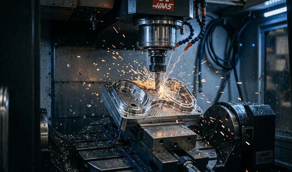
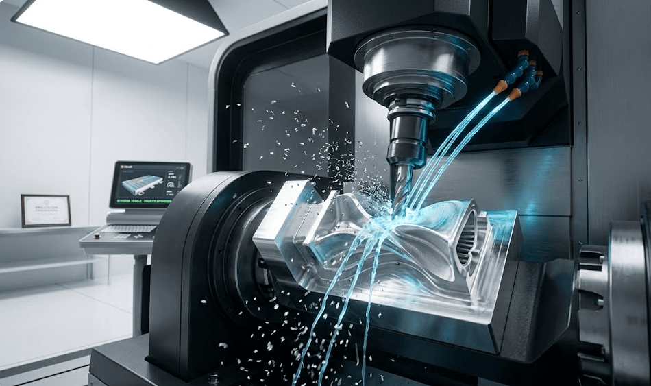
Multi-axis CNC machining center milling a complex aerospace metal component in a precision manufacturing facility
Chaoyang blog

How does precision CNC machining affect complex parts

A single out-of-tolerance feature does not just fail inspection — in fact, the consequences compound fast. Basically, it can ground a production line or trigger a lot of rejection. Meanwhile, downstream liability alone can dwarf the original machining cost. Therefore, procurement managers sourcing precision CNC machining services cannot treat tolerance capability as a secondary qualification. Ultimately, the machine tools, process controls, and inspection systems behind a machining partner determine whether complex parts ship on time. Or become an expensive rework event. The Real Cost of Tolerance Failure in Complex Part Production Most out-of-tolerance failures are not discovered at the machine — indeed, they typically emerge far later. They surface during assembly. A bearing housing 0.01 mm oversize. A connector terminal failing insertion force testing. A structural bracket failing fatigue analysis. All trace back to a radius ground 0.003 mm short of specification. By that stage, the cost is no longer just the part. Still, consider the full exposure: Rework and re-inspection consume 3–5× the original machining cost on complex geometries Assembly line stoppages in automotive production average $10,000–$22,000 per hour Lot rejections in aerospace programs can trigger First Article Inspection re-qualification — adding weeks to a program schedule Warranty escapes — where non-conforming parts reach the field — carry liability exposure that standard supplier agreements rarely limit adequately Furthermore, in 3C electronics, a connector housing out of tolerance by 0.005 mm can cause 100% rejection of a finished PCB assembly batch. Consequently, precision CNC machining services are not a cost category to optimise downward — they are a risk management decision. For facilities managing stamping dies and tooling inserts, the same logic applies to sourcing precision mould components from a qualified supplier. Why AWEA CNC Machining Centres and Multi-Process Capability Define Consistency Tolerance capability is not a claim — that said, it is also not a specification. In fact, it comes from specific equipment, operated in controlled conditions, and verified by traceable measurement. Specifically. CNC Machining Centres: YASDA High-speed CNC (Japan) — Spindle speed 200–40,000 RPM, accuracy ±0.002 mm. Used for complex 3D geometries and mirror-surface finishing on hardened tool steel. AWEA CNC Machining Centres (Taiwan) — Stroke 1,200 × 600 mm. Suited for die plates, structural brackets, and multi-feature components requiring 3- and 4-axis milling. AGMA CNC Machining Centres (Taiwan) — Stroke 1,600 × 800 mm. Handles larger workpieces with the same dimensional consistency. Vision Wild CNC Machining Centres (Taiwan) — Stroke 1,600 × 3,100 mm for long-travel work on progressive die bases and large fixture plates. For reference on what constitutes industry-accepted tight tolerance machining standards, the Society of Manufacturing Engineers documents process capability benchmarks widely used in North American supplier qualification programs. Grinding and EDM Processes: Moore Jig Grinding — Accuracy ±0.001 mm. Essential for guide pin bores, punch retainer fits, and precision hole location WASINO Profile Grinding (Japan) — Precision ±0.001 mm, Ra 0.05. Used for complex contour grinding on special-shaped die components Sodick Oil-based Wire EDM — Accuracy ±0.001 mm, Ra 0.05. Cuts hardened profiles and intricate geometries without contact force Seibu Water-based Wire EDM — Wire range φ 0.05–0.3 mm. Suited for fine-pitch connector tooling and high-speed roughing In practice, a complex part typically requires milling, grinding, and EDM in sequence. Notably, each process handoff at a single-process supplier introduces measurement error and scheduling risk. Accordingly, Chaoyang’s integrated capability keeps complex parts under one quality system. In-process CMM verification occurs at each stage; however, this is only possible when all processes share one quality system. How Chaoyang Verifies Every Part Before Shipment Chaoyang Hardware (spsunmold.com) is ISO 9001:2015 certified and operates a zero-defect inspection policy across both facilities. Specifically, every part ships after: Zeiss CMM inspection — Full 3D verification against customer CAD, traceable to national measurement standards Trimos 2D height gauge — Confirms step heights, shoulder depths, and datum-referenced dimensions Nikon profile projector and microscope — Optical verification of radii, chamfers, and thread profiles Rockwell hardness testing — Heat treatment compliance confirmed on every batch Material traceability documentation — Full certification supplied with each order Clients, including Amphenol, Hirose Electric, Foxconn, BYD, and Yamaha, qualify Chaoyang’s components directly into production without incoming re-inspection. Standard parts are complete in 7–15 working days. Additionally, prototypes for design validation are often completed faster. Complex multi-process components are quoted individually based on geometry and process sequence. Our capabilities extend beyond individual components — see how the same quality standards apply across our stamping die manufacturing programs. The Precision CNC Machining Services Right Partner Makes Conformance Repeatable Tolerance capability is binary in high-stakes manufacturing — a part either conforms or it does not. Moreover, non-conformance costs in aerospace, automotive, and 3C electronics are not linear with the degree of deviation. Consequently, procurement managers who qualify on equipment capability, inspection protocol, and ISO certification achieve lower total program costs. Fewer schedule surprises follow. Indeed, the right machining partner builds process controls that make conformance repeatable. Ultimately, complex parts deserve a supplier whose quality system can be audited and whose inspection data can be reviewed. FAQ: What tolerances can Chaoyang’s precision CNC machining services achieve? Chaoyang’s CNC machining centres achieve processing accuracy to ±0.002 mm on milled and turned features. Jig grinding and Wire EDM processes reach ±0.001 mm for critical hole locations and profile features. Surface roughness values reach Ra 0.05 μm on ground and EDM-finished surfaces. All dimensions are verified against customer CAD using Zeiss CMM equipment. Which raw materials and grades are available? Chaoyang machines hardened tool steel (SKD11, SKH51, H13), pre-hardened steel (NAK80, P20), aluminium alloys, stainless steel, and engineering plastics. Tungsten carbide components are also produced for ultra-high-cycle tooling applications. All materials ship with full certification and traceability documentation. What is the typical lead time for an order? Standard precision parts with defined geometry and tolerances are complete in 7–15 working days. Chaoyang’s team typically completes prototypes and single-off components for design validation faster than standard lead times. Lead times for multi-process parts requiring milling, grinding, and EDM in sequence are confirmed at quotation based on the specific process

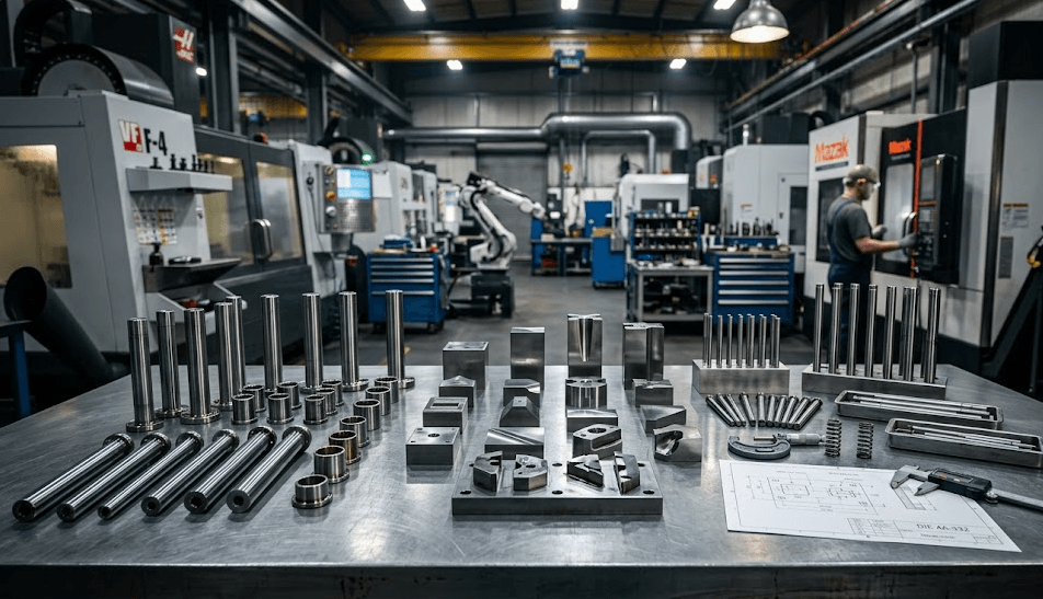
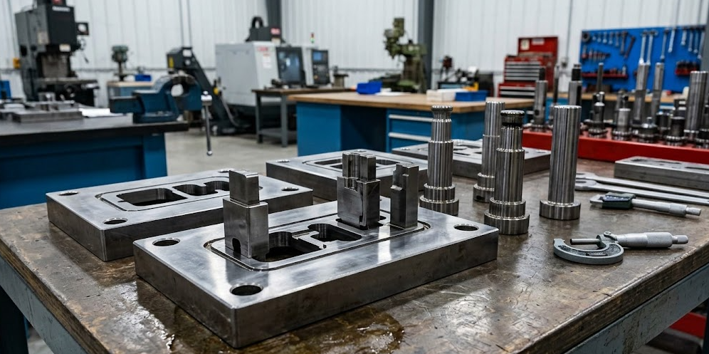
Precision mold components including guide posts, punch inserts, and ejector pins arranged on an inspection table in a CNC machining facility
Chaoyang blog

High-quality precision mold components can prevent costly production downtime

Unplanned Precision Mould Components failure does not just stop one machine. Basically, it triggers a cascade — halted lines, scrapped batches, overtime labour, and emergency tooling orders that arrive too late. Therefore, North American procurement managers and maintenance engineers increasingly treat precision mold components as a first-line defence, not a maintenance afterthought. Ultimately, the quality of the components inside your mold determines how long your production run stays profitable. Why Worn Components Are Costing You More Than You Think Most production downtime is not caused by catastrophic failure. It accumulates gradually — through worn guide bushings, fatigued ejector pins, and punch inserts that drift out of tolerance after millions of cycles. Consequently, every micron of wear compounds into dimensional variation, increased scrap rates, and eventual die crash. The real cost is rarely the replacement part. Consider what surrounds it: Line stoppage costs in automotive stamping average $10,000–$22,000 per hour, according to industry benchmarks Scrap and rework on out-of-tolerance 3C connector housings can consume 8–15% of the batch value Emergency tooling lead times from low-quality suppliers routinely add 3–6 weeks of exposure Secondary quality escapes — where defective parts reach assembly — carry warranty and liability consequences that dwarf the original tooling cost Furthermore, in aerospace and medical applications, a single out-of-spec component can trigger a full lot rejection and regulatory review. Indeed, the economics are clear: investing in high-quality precision mould components upfront costs far less than managing the failures they prevent. Poor-quality components affect every part of the tool — from guide systems to the precision stamping dies they support. Why Tight Tolerances and Material Selection Determine Service Life Material choice and machining precision are not independent decisions — they interact directly to determine how long a component performs in service. Tool steel selection by application: SKD11 (D2 equivalent) — High chromium cold work steel. Hardness range HRC 58–62. Suited for high-abrasion punch inserts and cutting dies in progressive stamping SKH51 (M2 high-speed steel) — Superior hot hardness. Used for fine-blanking punches and thin-section inserts operating at elevated cycle speeds NAK80 pre-hardened steel — Ideal for plastic injection mould cores and cavities requiring mirror-finish surface quality Tungsten carbide — Specified for ultra-high-cycle applications exceeding 50 million strokes, particularly in connector terminal stamping Machining processes that hold tolerance: Tight tolerances come from specific processes — not specifications alone. Chaoyang’s component manufacturing combines: CNC jig grinding — Achieves hole and slot accuracy to ±0.001 mm. Essential for guide post bores and punch-to-die clearance Wire EDM — Cuts complex profiles to ±0.002 mm without contact force or thermal distortion. Accordingly, thin-wall inserts and intricate punch geometries hold their designed geometry through the full cut CNC milling and turning (3-axis to 5-axis) — Handles complex 3D cavity forms and contoured stripper plates with full dimensional traceability Surface and profile grinding — Delivers surface roughness to Ra 0.02 μm. Critical for ejector pin bores and parting surface flatness Why tolerance directly drives downtime: A guide bushing manufactured to ±0.01 mm rather than ±0.002 mm allows measurably more lateral movement in the punch-die assembly. Over time, that movement accelerates edge wear, increases burr height on stamped parts, and shortens maintenance intervals. Notably, the difference in machining cost between the two tolerance grades runs to dollars — the difference in service life runs into production cycles. According to the Society of Manufacturing Engineers, documented process capability and traceability are the two most cited deficiencies in tooling supplier audits. Precision Components Are a Maintenance Strategy, Not a Line Item Production downtime is rarely random. Moreover, it traces back to specific, preventable failure points — most of them living inside the mould itself. Consequently, maintenance engineers who specify high-tolerance, heat-treated precision mould component are not spending more; they are extending service intervals, cutting emergency procurement events, and protecting per-piece economics on every run. Ultimately, the facilities that treat mould component quality as a production continuity investment are the ones that consistently hit cycle targets and keep their tooling costs predictable. FAQ: What tolerances can Chaoyang hold on precision mold components? Chaoyang’s machining processes achieve dimensional tolerances as tight as ±0.001 mm for jig-ground features and ±0.002 mm for wire EDM profiles. Surface roughness values reach Ra 0.02 μm on ground and polished surfaces. Every component is verified against customer CAD data using Zeiss CMM equipment before shipment. What materials are available for custom precision mold components? Chaoyang supplies components in SKD11, SKH51, NAK80, P20, H13, and tungsten carbide, as well as aluminium alloys and engineering plastics for non-wear applications. All materials ship with full certification and traceability documentation to support incoming inspection and lot control requirements. How long does a custom precision mould component order take? Standard tooling components — including guide posts, guide bushings, ejector pins, and punches in common sizes — ship within 3–5 business days. Custom components requiring wire EDM profiling, jig grinding, or complex 5-axis CNC machining are complete in 7–15 working days, depending on geometry and quantity.

Heavy-duty transfer die stamping press forming large automotive structural component with robotic transfer arms visible in industrial facility
Chaoyang blog

Is the transfer stamping process suitable for large, complex parts?

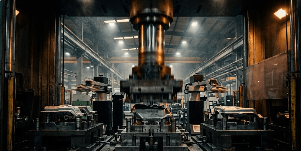
Transfer die stamping separates the blank from the metal strip at the first station. It then uses mechanical or robotic transfer systems to move each part through subsequent forming stations independently. Basically, this makes it the preferred process for large, deep-drawn, and geometrically complex components that progressive dies simply cannot handle. Transfer Die vs. Progressive Die Stamping Feature Transfer Die Stamping Progressive Die Stamping Part Transfer Method Mechanical fingers/robotic arms Carried by the metal strip itself Best for Part Size Large, deep, or complex geometry Small to medium, flat or shallow Material Efficiency High (parts are cut free early, less scrap) Moderate (requires carrying web) Why Transfer Die Stamping Outperforms Progressive Dies for Complex Parts Not every stamping challenge fits a progressive die. Basically, progressive dies work well for small, high-volume parts. The metal strip carries each blank through stations connected by a web. However, that web becomes a structural liability as part size increases or draw depth deepens. Consequently, transfer die stamping removes that constraint entirely — opening a capability that progressive tooling cannot match. The distinction comes down to blank handling. In progressive stamping, the part stays attached to the carrier strip at every station. Therefore, the strip must remain intact, limiting how aggressively each station can form the material. The transfer die stamping separates the blank at station one. It moves as a free part from that point forward. As a result, each subsequent station applies full forming force from any angle — without the restrictions a connected carrier imposes. Overcoming Progressive Die Limits with Transfer Die Stamping Progressive dies reach their practical ceiling at moderate draw depths. Specifically, draw depths exceeding 50–60% of blank diameter cause the carrier web to lose structural integrity. It distorts or tears under the load. Furthermore, large blanks — floor pans, door inners, structural frame rails — generate forces that exceed what a progressive strip can absorb at the carrier bridges. Transfer die stamping eliminates both constraints. Each station receives the blank as a discrete, unsupported part. Therefore, tooling engineers design each station around the forming requirement alone — not around strip limitations. Consequently, draw ratios that would tear a progressive strip become achievable. Blank sizes that progressive tooling cannot handle become standard production runs. For heavy machinery engineers, this distinction is direct. It determines whether a part needs secondary operations, additional tooling investment, or a geometry redesign to fit process limitations. Transfer Die Stamping Material Efficiency: Eliminating the Carrier Web Progressive dies require a carrier web — the scrap skeleton that holds blanks together as the strip advances. In high-volume production, that web is consistent and unavoidable material loss. Specifically, web scrap represents 15–30% of total material consumption per part. The exact figure depends on blank size and nesting efficiency. Transfer die stamping eliminates the web. The blank cuts to near-net shape at station one. It then transfers forward as a finished blank. Therefore, material utilisation improves directly and measurably. For Tier 1 suppliers running high-volume steel or aluminium programs, scrap reduction delivers a significant per-part cost advantage. Moreover, scrap handling, baling, and disposal costs decrease proportionally. Procurement managers should include that secondary saving in total cost of ownership calculations. For details on how SPSUNMOLD optimises blank utilisation across tooling programs, the manufacturing capabilities page covers the approach in full High-Precision Handling in Transfer Die Stamping via Automated Robotic Systems The robotic transfer system is a precision positioning device. It determines part location accuracy at every forming station. Specifically, modern servo-driven systems achieve positioning repeatability of ±0.05mm or better. That consistency holds across millions of production cycles. This precision directly affects dimensional consistency in the finished part. Automotive structural components carry tight positional tolerances. Chassis nodes, B-pillar reinforcements, and longitudinal frame members all assemble directly to body-in-white structures. Consequently, transfer die stamping’s positioning consistency supports the GD&T requirements that Tier 1 and Tier 2 suppliers must meet under OEM sourcing agreements. Robotic end-of-arm tooling additionally provides six-axis flexibility. It handles deep-drawn shells and asymmetric structural brackets without distortion — a capability mechanical fingers cannot reliably deliver. Automotive Chassis Components and Structural Frame Members Chassis longitudinal rails, crossmembers, and floor pan assemblies are the core volume application for transfer die stamping. A full-length floor pan blank for a mid-size passenger vehicle exceeds 1,200mm in length. It requires draw depths of 80–120mm in multiple directions simultaneously. Progressive tooling handles neither requirement. Transfer die stamping, therefore, handles both as standard process parameters. Chassis components also carry strict load path requirements. Material thinning during the draw process must stay within specification. Transfer tooling allows the die engineer to design draw beads, blank holder pressure profiles, and station sequences that control metal flow precisely. Wall thickness in critical load zones meets structural specification after forming. ASM International’s metal forming and stamping technical library documents the material behaviour and tooling design principles that govern multi-station draw sequence mechanics for structural automotive components. Deep-Drawn Shells and Housings for Heavy Industry Heavy machinery and commercial vehicle applications demand deep-drawn housings and structural shells. These parts exceed the draw capability of progressive tooling. Hydraulic cylinder end caps, differential housings, and transmission case components routinely require draw depths of 100–200mm. Tight wall thickness tolerances apply throughout the drawn section. Transfer die stamping handles these requirements through controlled multi-station draw sequences. The blank progresses through a redraw station, an ironing station, and a trimming station. Each applies only the forming increment that the material can absorb at that stage. The finished part achieves the required draw depth without splits, wrinkles, or excessive thinning. B-Pillar Reinforcements and Door Structural Inners B-pillar reinforcements, door ring inners, and sill reinforcements combine large blank size with complex geometry and tight assembly tolerances. A B-pillar reinforcement for a full-size truck platform requires blanks exceeding 900mm in length. It also requires multiple compound curves and precise flange geometry for spot weld assembly to the body-in-white. Robotic transfer arms handle the large, curved blank geometry without distortion between stations. Moreover, station-by-station forming distributes strain across multiple operations.

Deep drawn stamping die forming a seamless stainless steel metal enclosure for EV and aerospace applications
Chaoyang blog

Deep-draw stamping is the solution for complex metal enclosures

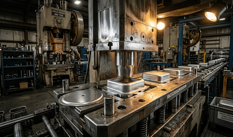
Deep drawn stamping produces seamless, leak-proof metal enclosures where part depth exceeds diameter. Basically, no welding, no joints, no failure points. Therefore, for EV battery shells, aerospace sensor housings, and industrial motor enclosures, it delivers structural integrity that fabricated alternatives cannot match. Ultimately, the process is defined by material flow — not material removal. Why Choose Deep Drawn Stamping for Industrial Metal Enclosures? Deep drawn stamping forms metal enclosures where depth exceeds diameter — producing seamless, leak-proof, high-strength parts in a single operation. For EV battery shells, aerospace sensors, and motor housings, the process eliminates weld seams and joint failures. As a result, deep-drawn components outperform fabricated enclosures on every structural and dimensional metric. Seamless vs. Welded: A Direct Manufacturing Comparison Not all metal enclosure manufacturing methods deliver equal results. Here is how they compare: Deep Drawn Stamping vs. Standard Metal Stamping Feature Deep Drawn Stamping Standard Progressive Stamping Part Geometry Cylindrical, box-shaped, seamless enclosures (Depth > Diameter) Flat, shallow bends, brackets, and clips Material Integrity Seamless construction (Water/Dust proof) May require welding for enclosures Best Applications EV battery casings, motor housings, and medical sensors Connectors, lead frames, shielding covers Material Flow, Not Material Removal: The Physics Behind the Process Deep drawn stamping works by flowing metal — not cutting it, grinding it, or welding it. Specifically, a punch forces a flat blank into a die cavity, compressing and redirecting material into the desired enclosure geometry. In turn, the metal grain structure remains continuous throughout the part wall. Therefore, a deep-drawn EV battery shell carries no internal stress concentrations from heat-affected zones or machined surfaces. The critical engineering variable is the draw ratio — blank diameter divided by punch diameter. According to the Society of Manufacturing Engineers, draw ratios above 2.0 typically require a redraw operation to avoid tearing. That said, Chaoyang engineers design draw ratios and redraw sequences for each part geometry, ensuring material flow stays within formability limits. Moreover, blank holder force is equally critical. Without sufficient pressure, the flange material wrinkles as it flows into the die. By contrast, excessive blank holder force restricts material flow and causes tearing at the punch radius. Consequently, Chaoyang’s tooling design process includes finite element analysis of blank holder force distribution for every new deep-drawn die program. Die Precision Determines Wall Thickness Uniformity The die is not just a shape — it is a precision instrument. In fact, punch-to-die clearance directly controls wall thickness in the drawn part. Specifically, a clearance set too tight causes ironing. Clearance set too loose allows material to fold rather than flow, producing wall thickness variation that fails dimensional inspection. At Chaoyang, punch and die cavities are machined on YASDA high-speed CNC centres to positional tolerances of ±0.002mm. As a result, clearance consistency holds across the full draw depth. Furthermore, the radii are ground to a mirror finish on Moore Jig Grinders, minimising friction-induced thinning at the most stress-concentrated points in the draw cycle. Additionally, the material selection matters as much as dimensional accuracy. For high-volume automotive and EV programs, Chaoyang specifies D2 or SKD11 tool steel at 58–62 HRC surface hardness. In turn, this resists galling from high-strength steel and stainless steel blanks — maintaining accuracy across millions of draw cycles. Material Selection Defines the Performance Envelope of Deep Drawn Enclosures Not every material draws equally. In practice, formability, springback, and surface finish vary significantly across alloy families. Specifically, the correct materials for industrial deep drawn enclosures are: Stainless Steel 304 and 316. Both offer excellent corrosion resistance and high work-hardening rates. 304 is standard for motor housings and fluid-handling enclosures. 316, by contrast, suits marine and chemical processing applications where chloride resistance is required. Aluminium 3003 and 5052. Aluminium draws with lower forming forces than steel. Furthermore, it is the preferred material for aerospace sensor housings and lightweight EV enclosures where weight reduction drives the design. Copper and Brass. Both offer exceptional formability and suit electrical connector housings, thermal management enclosures, and RF shielding applications. In addition, copper’s thermal conductivity makes it irreplaceable in high-power EV and industrial electronics enclosures. Deep Drawn Stamping Delivers What Fabricated Enclosures Cannot Deep drawn stamping is the correct process for any metal enclosure where structural integrity, dimensional consistency, and leak-proof performance are non-negotiable. After all, EV battery shells, aerospace sensor housings, and industrial motor enclosures operate in environments where fabricated alternatives fail. Indeed, the seamless grain structure, uniform wall thickness, and high-volume cost efficiency of deep drawn parts are simply not replicable by welding or machining. Accordingly, Chaoyang engineers deep-drawn stamping dies for automotive, aerospace, and industrial programs — with full tooling design, CNC machining, and die tryout capabilities available through the precision dies team.

CNC Machining Center cutting a precision stamping die component in an industrial manufacturing facility
Chaoyang blog

The precision of a CNC machining center is the cornerstone of high-quality stamping dies.

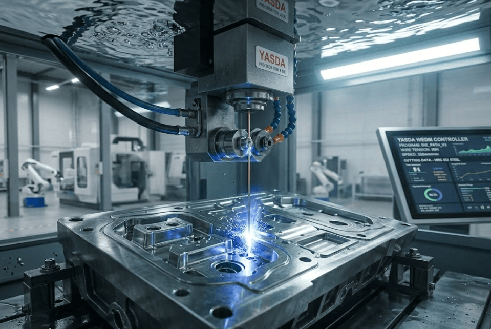
A high-end CNC Machining Center delivers sub-micron dimensional accuracy, eliminates geometric variation across complex die components, and compresses lead times without sacrificing consistency. For automotive and electronics die programs, machine capability is not a differentiator. In fact, it is the baseline requirement for staying in the supply chain. Standard Machining vs. Ultra-Precision CNC Machining Centre: Why the Gap Matters Not all CNC machining is equal. Standard CNC machining centres operate within tolerances of ±0.01mm to ±0.05mm. Stamping die components — punches, die plates, guide bushings, and stripper plates — require tolerances of ±0.002mm or tighter. In practice, that is a different discipline entirely. At that level, however, factors that standard machining ignores become the primary sources of error. Heat and vibration are the two primary sources of dimensional error in precision machining. Specifically, a 1°C spindle temperature shift can produce several micrometres of positional drift — enough to push a punch-to-die clearance out of tolerance. Similarly, floor-transmitted vibration introduces surface irregularities on sealing faces and guide bores. Therefore, temperature-controlled rooms, spindle cooling systems, and vibration-isolation foundations are baseline operating conditions. None of these is optional. In short, ultra-precision machining is an environmental discipline as much as a mechanical one. The machine specification is only one part of the equation. CNC Machining Center Equipment That Defines Precision Die Quality Specifying tolerances on a drawing is straightforward. Consistently achieving them across a production run, however, requires the right equipment — operated in the right environment. Comparison of High-Precision Equipment at SPSUNMOLD Equipment Type Brand / Model Primary Application Precision Level High-Speed CNC Machining Center YASDA (Japan) Complex geometry, micro-scale parts ±0.001 mm Jig Grinder Moore (USA) Ultra-precision holes and slots Sub-micron Wire EDM Sodick / Seibu Intricate die cutting & punching High-finish surface YASDA High-Speed CNC: Complex Geometry and Mirror-Surface Finishing The YASDA CNC machining center is purpose-built for precision die and mold work. Its thermal compensation system actively monitors and corrects for spindle growth during operation — a critical capability when machining complex 3D geometry on hardened tool steel. Furthermore, its high-speed spindle delivers the surface-finish consistency required for die-sealing faces and ejector pin bores, where surface roughness directly affects part release quality and die service life. For electronics and semiconductor tooling where feature sizes fall below 0.5mm, YASDA’s positioning accuracy of ±0.0005mm is the minimum acceptable specification. Moore Jig Grinder: Ultra-Precise Hole and Slot Grinding The Moore Jig Grinder remains the industry benchmark for hole location accuracy in precision tooling. In stamping die construction, guide pin bores, punch retainer holes, and pilot hole locations must maintain positional tolerances of ±0.001mm or tighter across the full die plate. The Moore achieves this through its precision air-bearing spindle and thermally stable cast iron structure. As a result, die assemblies built around Moore-ground components exhibit the guide clearance consistency that high-speed progressive dies demand — often running at 400 to 600 strokes per minute without perceptible wear over millions of cycles. Sodick and Seibu Wire EDM: Intricate and Non-Standard Die Cutting Wire EDM is the process of choice for die components that cannot be machined by conventional cutting — hardened steel profiles, internal radii below 0.1mm, and complex aperture geometries. Sodick’s linear motor drive eliminates backlash and servo lag, delivering measurably better corner accuracy on complex die apertures. This is critical for connector terminals, IC lead frames, and fine-pitch electronics components, where profile deviation of 0.003mm translates directly into dimensional rejection. Seibu’s water-based Wire EDM complements the Sodick with high-speed roughing capability on larger die sections — together covering the full Wire EDM range from ultra-fine electronics tooling to heavy automotive progressive die components. CNC Precision and Die Sets: How Integration Determines Final Performance A precision-machined component is only as good as the die set it assembles into. When CNC-machined die components are specified to MISUMI or HASCO dimensional standards, the assembly process becomes deterministic rather than iterative. Specifically, punch retainer plates, die plates, and stripper assemblies drop into position within tolerance — eliminating hand-fitting and shimming. As a result, the tryout time is reduced by 30 to 50% compared to non-standardized builds, and first-hit part quality is measurably higher. For procurement managers evaluating suppliers, compatibility with MISUMI or HASCO is a direct indicator of process maturity. FAQ: What tolerance level should a CNC Machining Center achieve for stamping die components? For general die plate features, ±0.005mm is the working minimum. For critical locations — guide pin bores, punch retainer fits, and pilot hole positions — the requirement is ±0.001mm to ±0.002mm. Any supplier unable to demonstrate these capabilities with traceable inspection data should not be considered for precision die programs. Why does surface finish matter in stamping die machining? Surface finish on die sealing faces, guide surfaces, and ejector pin bores directly affects die performance and service life. A rough surface accelerates wear and can introduce micro-cracking in hardened steel under cyclic press loading. Therefore, mirror-finish grinding on critical faces is a functional requirement, not an aesthetic one. What certifications should a precision die manufacturer hold? ISO 9001:2015 is the baseline requirement for any precision die supplier entering a North American or European supply chain. According to the Society of Manufacturing Engineers, documented process capability and traceability are the two most cited deficiencies in tooling supplier audits.

YASDA high-speed CNC machining center operating in a precision tool and die manufacturing facility
Chaoyang blog

Why Does YASDA High-speed CNC Machining Matter for Tight Tolerance Parts?

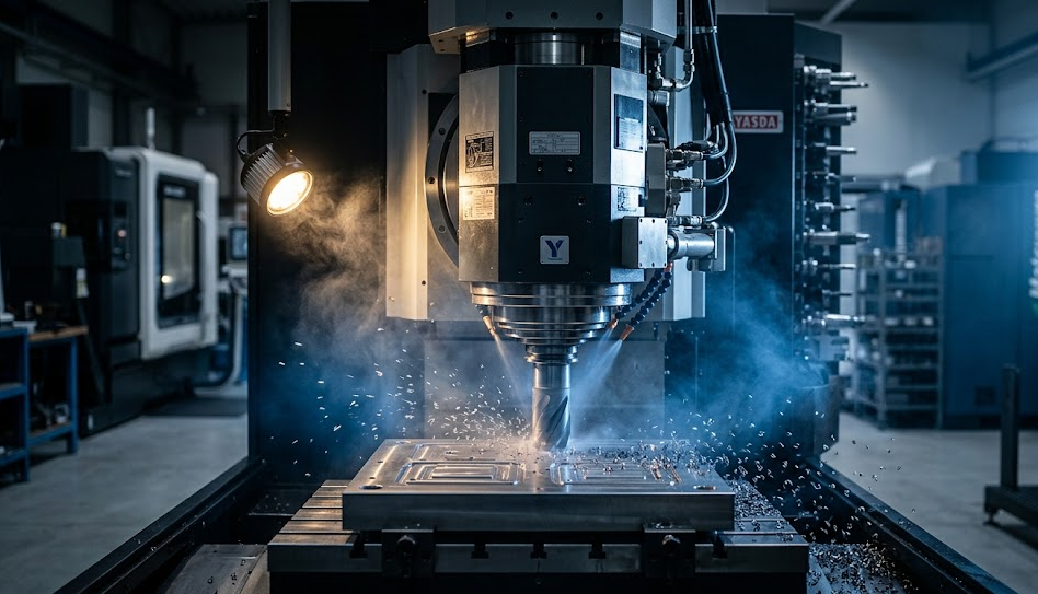
YASDA high-speed CNC machining sets a different standard for tight-tolerance parts. Most shops claim ±0.005mm. Yet few consistently deliver it. In fact, the gap between promise and delivery usually comes down to one thing: the machine on the floor. At Chaoyang, we work with manufacturers who build progressive dies and automation jigs where a 2-micron drift is a production failure. Specifically, this article answers which machine capability questions to ask—and why the answers determine your outcome. What Makes YASDA High-speed CNC Different From Standard Machining Centers? Three engineering decisions separate a YASDA from everything else on the market. Standard mills skip all three. Start with the guideways. YASDA slideways are hand-scraped by craftsmen—manually lapped to sub-micron flatness, not ground by machine. That process removes the micro-stick that conventional linear guides produce at low feed rates. On a standard VMC, that stick translates directly into waviness on finish surfaces. It is a problem most shops live with. YASDA eliminates it at the source. Thermal drift is the second issue. Run a conventional spindle for four hours, and it grows 15–20 micrometers as heat builds in the ballscrews and casting. Most machines have no answer for this. YASDA runs coolant through the spindle core and closes the loop with thermal feedback—dimensional stability holds through the full shift, not just the first setup piece. The third factor is how the machine is built. YASDA castings are substantially heavier than the working envelope requires. That mass translates into static and dynamic stiffness that kills chatter during fine interpolation passes. A 0.003mm profile tolerance on a punch face stays within spec. For reference, ISO 286-1 places that capability at IT3 and below—a tolerance grade the vast majority of machining centers cannot reliably hold. What Are the Red Flags When Vetting Suppliers for YASDA High-speed CNC Machining? The market is full of general-purpose shops quoting precision-grade work. Four signals, however, tell you which is which. Start with the equipment list. A credible high-precision shop names specific models: YASDA, Moore Jig Grinder, WASINO, and Sodick. “Advanced CNC equipment” with no brand specifics means commodity machines running tolerance-priced jobs. That gap matters more than any brochure claim. Temperature control is the next thing to verify. Sub-micron work requires ±1°C ambient stability. A 5°C swing, for instance, introduces thermal expansion errors that invalidate micron-level measurements. If the shop floor and inspection lab are not climate-controlled, the numbers on the inspection report are therefore estimates—not measurements. Process documentation is equally telling. A reliable precision supplier produces tool life logs, in-process inspection sheets, and job travelers for every order. Without these, however, quality depends on operator memory. That means it varies, and variance at micron-level tolerances is a rejection. Finally, ask about outsourcing directly. Some suppliers accept precision orders and subsequently subcontract the critical operations without disclosure. The question is simple: is 100% of the machining performed in-house on your own equipment? Chain-of-custody over tight-tolerance parts breaks the moment the job leaves the facility—and with it, your quality guarantee. Standard CNC Milling vs. True Sub-micron Machining Services Standard CNC milling holds ±0.01–0.05mm under normal conditions. Surface finish, accordingly, lands at Ra 0.8–1.6μm. For structural housings and brackets, that works. True sub-micron machining, however, targets ±0.001–0.003mm with Ra 0.05–0.2μm. At this level, tool wear shifts dimensions in real time. Machine rigidity is therefore the foundation—deflection under cutting load on a light frame causes measurable error that no operator skill can recover. Moreover, thermal drift is managed actively, not tolerated. For progressive die components, precision jig plates, and automation fixtures that mate to micron-level tolerances, only sub-micron-capable machining delivers consistent results across a full batch. In addition, ASME B89.1.12 covers the performance evaluation standards for CMM verification of such components—another layer of process your supplier must support. How Do Elite Machine Tools Actually Lower Your Total Cost? The objection is predictable: YASDA machining costs more per hour. That is true. It is, however, irrelevant if you calculate the cost correctly. A supplier running general-purpose equipment on precision work typically produces 15–30% scrap on critical features. As a result, you absorb the re-run cost, the extended lead time, and—if nonconforming parts reached your assembly line—the downstream rework. The machine hour rate on the original quote then becomes a rounding error against those losses. Parts off a YASDA, by contrast, arrive at a surface finish that needs no secondary hand-polishing on functional faces. Manual bench lapping introduces human variability. Two technicians working the same die section will, for example, produce different results. Eliminate that step, and you consequently eliminate the variability. Die life extends. Maintenance cycles lengthen accordingly. Near-zero scrap on precision features is a direct output of machine capability. When the process holds tolerance by design—not by operator effort—inspection pass rates therefore approach 100%. You stop paying for sorting. You stop paying for expedited replacements as well. The real question is not what the machining costs. Rather, it is what a nonconforming precision component costs once it reaches your production floor. Which Quality Standards Must Your Precision Parts Manufacturer Hold? Machine capability without measurement capability is a process without a feedback loop. ISO 9001:2015 certification is the baseline. It confirms documented procedures, traceable records, structured corrective action, and scheduled management review. For procurement teams, this therefore means quality outputs are repeatable and auditable—not dependent on which shift is running. Beyond the QMS, verify the measurement hardware. Zeiss CMM systems are the global reference standard for dimensional verification of precision parts. Specifically, contact and optical probing confirm die plate profiles, punch positions, and jig datums against CAD nominal. Supporting equipment should also include height gauges, profile projectors, and measuring microscopes. A supplier measuring finished parts with calipers, consequently, cannot confirm sub-micron compliance. The inspection environment matters too. Zeiss CMM readings are only valid at 20°C ±1°C. An uncontrolled lab, therefore, produces directional data, not metrological data. Ask for calibration certificates and ambient temperature logs as well. Dongguan Chaoyang Hardware Products Co., Ltd. operates YASDA high-speed CNC machining centers alongside Moore JG, WASINO PG, Sodick

Precision stamping die components manufactured by experienced stamping die manufacturer showing die plates and punch inserts
Chaoyang blog

How to Choose the Right Stamping Dies Manufacturer for Your Project

Choosing the wrong stamping dies manufacturer doesn’t just slow down a project — it can compromise part quality, blow out tooling budgets, and create production problems that take months to fix. The right manufacturer gets your geometry right the first time, holds tolerances that match your spec sheet, and builds tooling that stays functional through millions of cycles. Here is what to evaluate before you commit. What Does a Stamping Dies Manufacturer Actually Do? A stamping die manufacturer designs, machines, and assembles the tooling used to cut, bend, and form sheet metal into precise components. More specifically, this includes progressive dies, compound dies, blanking dies, and custom die sets built to client specifications. The quality of the die determines the quality of every part produced from it, which is why manufacturer selection matters so much upstream. Chaoyang specializes in progressive stamping dies for industries where tolerances are unforgiving — automotive, 3C electronics, aerospace, and IC semiconductor manufacturing. In addition, material thickness ranges from 0.1 to 2.0mm, with die components made from carbide, ceramic, powder metals, or conventional tool steel, depending on the application. What to Evaluate When Choosing a Stamping Die Manufacturer Not all stamping die manufacturers are built the same. In fact, the gap between a capable shop and a precision-focused one shows up immediately in the tolerances they can hold and the equipment they use to hold them. Equipment and Machining Capabilities The machines on the shop floor tell you more than any brochure. A serious stamping die manufacturer invests in equipment built for sub-micron accuracy — jig grinding, profile grinding, wire EDM, CNC machining, and surface grinding at a minimum. At Chaoyang, the toolroom runs Moore Jig Grinders, WASINO Profile Grinders, Seibu Wire EDM, Sodick Oil-based Wire EDM, and AWEA CNC Machining Centers. As a result, having all of them in-house eliminates the handoff delays and tolerance stack-ups that come with outsourcing critical operations. Similarly, in-house CMM and optical comparators are non-negotiable for any manufacturer claiming precision output. Without them, you are relying on the manufacturer’s word rather than traceable measurement data. Similarly, in-house CMM and optical comparators are non-negotiable. Without them, you’re relying on the manufacturer’s word rather than traceable measurement data. Tolerances and Material Expertise Ask for documented tolerance capability, not just claims. Progressive dies for electronics and semiconductor applications routinely require single-digit micron tolerances. Although general machining shops can produce dies, they often lack the grinding and EDM precision needed for micro-component work. In addition, the material selection — carbide for high-wear applications, powder metals for complex geometries — directly affects tool life across high-volume runs. Quality Certifications ISO 9001:2015 certification is a baseline, not a differentiator. However, it confirms a documented quality management system with traceable processes. Chaoyang is ISO 9001:2015 certified across both its Dongguan and Nantong facilities. Beyond certification, look for CMM-based dimensional verification and documented tryout processes before dies ship. Industry Experience A stamping dies manufacturer with a narrow application history may struggle with your geometry, even if their equipment is capable. On the other hand, manufacturers with experience across automotive, aerospace, and electronics have encountered — and solved — a broader range of tooling challenges. Chaoyang has served automotive, communications, aerospace, 3C electronics, IC semiconductor, and home appliance clients since 2005. Red Flags to Watch For No in-house grinding or EDM means critical operations are outsourced — introducing lead time risk and tolerance uncertainty. Similarly, vague answers about measurement systems suggest quality control happens by eye rather than by instrument. In fact, an inability to provide die tryout documentation before shipment is a significant red flag for any high-volume tooling project. Why Chaoyang Chaoyang has been manufacturing precision stamping dies since 2005, with over 180 employees across two facilities. Visit the precision dies page for the full tooling range, and the Manufacturing Capabilities page for equipment details. The Precision Metalforming Association maintains useful industry standards on die fabrication quality. What is the difference between a progressive die and a compound die? A progressive die performs multiple operations across a series of stations as the strip feeds through the press. As a result, each stroke produces a finished part. A compound die, on the other hand, performs all operations simultaneously in a single station — better suited for simpler geometries with tight concentricity requirements. How do I evaluate a stamping dies manufacturer’s tolerance capability? Ask for documented process capability data on your part geometry. In addition, confirm what measurement equipment they use and whether inspection reports ship with the die. A manufacturer that cannot provide CMM data cannot verify the tolerances they claim. What materials are stamping dies made from? Typically, hardened tool steel, carbide, ceramic, or powder metals. Although tool steel is more economical, carbide delivers significantly longer tool life for high-speed progressive dies running millions of cycles. The right stamping die, the manufacturer proves capability through documented tolerances, traceable inspections, and relevant application history — not just a capabilities list. Ask the hard questions before tooling starts.

tooling dies sets showing upper lower die shoes guide posts and bushings for precision metal stamping
Chaoyang blog

What Are the Key Components of Tooling Die Sets in Precision Stamping?

Tooling dies sets are the structural backbone of every metal stamping operation. A single misalignment in the guide system causes punch breakage, dimensional drift, and unplanned downtime. However, most quality failures in stamping do not start with bad press settings or wrong material — they trace back to the die set itself. Therefore, understanding what each component does, what it is made from, and what happens when it fails is the starting point for any serious conversation about stamping quality. What Are the Components of a Tooling Dies Set? Tooling dies sets consist of four primary components: the upper die shoe, the lower die shoe, guide posts, and guide bushings. Together, these elements form a precision-aligned housing that holds punch and die components in exact registration throughout every stroke of the press — from the first part to the millionth. Tooling Dies Set Components: Function and Material Reference Component Name Primary Function Common Materials Upper Die Shoe Mounts and supports the punch assembly; transfers press force downward High-grade steel, cast iron (heat-treated for precision sets) Lower Die Shoe Holds the die block and provides the foundation for the entire set High-grade steel, cast iron (heat-treated for precision sets) Guide Posts Maintain precise alignment between upper and lower shoes during each stroke Hardened tool steel, case-hardened steel, carbide (high-wear applications) Guide Bushings Provide the mating surface for guide posts; control lateral movement and reduce friction Hardened steel, bronze, and self-lubricating composite materials How Tooling Dies Sets Components Affect Stamping Precision Each element in a tooling dies set plays a distinct role. Specifically, one failed component degrades the entire assembly. In high-speed progressive stamping, that degradation happens fast. Upper and Lower Die Shoes The die shoes form the structural platform of the entire set. First, machinists must grind them flat and parallel to within microns. Any deviation introduces a tilt that compounds with every press stroke. Because the shoes absorb the full stamping impact, their material grade and heat treatment determine how long the set holds its geometry. Consequently, an inadequately hardened die shoe deforms over time. The punch-to-die clearance shifts. Parts drift out of tolerance — with no visible mechanical failure to alert the operator. Guide Posts Guide posts control the lateral position of the upper shoe throughout every stroke cycle. Specifically, stamping presses generate significant lateral forces — especially under off-center loading. Therefore, manufacturers must hold extremely tight cylindrical tolerances on every post. A taper or surface irregularity of just 0.003mm accelerates bushing wear and introduces play into the alignment system. Consequently, the punch contacts the die at an angle. The result: burring, uneven cut edges, and in severe cases, catastrophic punch breakage. Guide Bushings: Wear Control in High-Cycle Stamping Dies Bushings take the majority of wear in normal operation. First, manufacturers bore them to match the post diameter with controlled clearance — typically 0.005mm to 0.015mm depending on speed and load. Because bushings act as the sacrificial wear component by design, material selection drives service intervals. Bronze and self-lubricating composites work well in high-cycle applications. However, semiconductor and 3C electronics tooling often requires dry-running engineered composites to avoid contamination. Consequently, wrong bushing material selection ranks among the most common — and most preventable — causes of early die set failure. The Foundation of Every Precision Stamping Operation No stamping result exceeds the quality of its die set. The shoes establish the geometric baseline. Guide posts enforce alignment under dynamic load. Bushings absorb wear and protect that alignment across millions of cycles. When engineers specify all four components correctly — right material, right hardness, right tolerances — tooling dies sets deliver consistent part quality across the full production life of the tool. For industry standards on precision stamping tooling, refer to the Precision Metalforming Association (PMA). That consistency is the only metric that matters in high-volume precision manufacturing.

metal stamping die 1(1)
Chaoyang blog

What does the micro-component stamping solution for metal stamping die entail?

Stamping micro-components demands a higher level of precision and stability than standard stamping operations. Micro-parts such as miniature springs, connectors, and electronic terminals require specialized metal stamping dies; these dies must offer precise forming accuracy, repeatable tolerances, and long-term durability. In solutions tailored for stamping micro-components, meticulous design, material selection, machining processes, assembly, and inspection are essential to ensure consistent part quality. An optimal metal stamping die solution must strike a balance between speed, precision, durability, and maintainability; therefore, we will outline exactly what constitutes a comprehensive metal stamping die solution. Design and Material Considerations for Micro Metal Stamping Die Micro-part stamping differs significantly from traditional stamping due to the extremely small part dimensions, the thinness of the materials used, and the exceptionally tight tolerance requirements. Even a minute dimensional deviation can render a part unusable. Consequently, precision metal stamping die solutions must exhibit high repeatability, maintain shape integrity, and prevent the deformation of intricate features. Furthermore, micro-parts are highly sensitive to defects such as burrs, scratches, and surface irregularities. During production, operators need to carefully control key factors, such as die clearance, punch-to-die alignment, and strip feeding accuracy, to keep manufacturing errors to a minimum. A deeper analysis of material behavior at the microscale is also imperative. Thin metals often exhibit greater variability regarding springback, edge cracking, and stress distribution. Before finalizing a die design, engineers must validate the forming limits through simulation or prototyping to ensure that the resulting micro-parts meet rigorous dimensional and functional specifications. Principles of Metal Stamping Die Design A successful metal stamping die begins with meticulous planning. The alignment of die components, the logical sequencing of operations, and ease of maintenance are critical to ensuring stable performance. Within a progressive die, each station must execute a single, distinct operation; this approach minimizes the risk of overstressing the material and preserves the integrity of the tolerances. The machining of precision metal stamping dies demands close attention to detail, encompassing factors such as edge condition, punch geometry, and blanking accuracy. The design process must also account for thermal effects, lubrication management, and stress distribution. Our ultimate goal is to produce molds capable of manufacturing highly uniform micro-parts while minimizing downtime, maintenance costs, and the likelihood of defects caused by material deformation or mold wear. Material Selection and Surface Treatment Tool steels, cemented carbides, or specially formulated wear-resistant alloys are typically employed to withstand repetitive, high-intensity operations without compromising dimensional accuracy. Surface treatments, such as nitriding, PVD coating, or specialized anti-friction finishes, help reduce wear, minimize burr formation, and facilitate part ejection during stamping. By carefully balancing material hardness, toughness, and surface characteristics, engineers can ensure the mold’s longevity over extended use. These factors are particularly critical in micro-part stamping, as even slight wear can compromise the integrity of tiny, intricate structures, leading to increased scrap rates and production downtime. Selecting the appropriate combination of substrate and coating constitutes the second step toward enhancing overall process stability. For instance, low-friction coatings can reduce heat generation during stamping, thereby helping to maintain dimensional accuracy throughout prolonged production runs. Metal Stamping Die Manufacturing, Machining, and Process Optimization High-precision machining is the most critical phase in developing metal stamping mold solutions. Processes such as CNC milling, wire EDM, precision grinding, and lapping are widely utilized in the fabrication of micro-part molds to achieve the required tolerances. At Chaoyang, we employ custom fixtures and clamping systems to ensure stability during machining, thereby preventing deformation. By leveraging these precision-machining techniques, manufacturers can ensure that metal stamping molds reliably produce complex micro-parts in high-efficiency, high-volume production environments. Beyond machining precision, process optimization is essential; we ensure that every machining step follows a controlled sequence to prevent error accumulation. Intermediate inspections are frequently conducted to verify dimensional compliance before proceeding to the next stage. In our machining facility, automated measurement systems are integrated directly into the workflow, further enhancing precision and efficiency. Progressive Die Design and Feed Stability for Metal Stamping Die Because progressive dies can perform a series of consecutive operations within a single material feed cycle, they are the ideal choice for the mass production of micro-parts. We ensure that our metal stamping die solutions incorporate precise feed control, alignment, and station sequencing to minimize errors and maintain consistency in part geometry. Our robust feeding systems reduce the likelihood of misfeeds, material stretching, and burr formation, which are particularly critical when working with thin or fragile materials. To further enhance feeding stability, our production lines typically integrate high-precision feeders, sensors, and control systems. These technologies enable real-time monitoring and adjustment, thereby ensuring operational stability. By combining mechanical precision with intelligent control systems, our metal stamping dies achieve new heights in performance and reliability. Delivering Comprehensive, High-Quality Solutions The stamping of micro-components relies on rigorous design, meticulous material selection, precision machining, careful assembly, and strict quality control. We view the metal stamping die as a fully integrated system, enabling us to produce high-precision micro-components with minimal waste and maximum efficiency. This comprehensive solution ensures repeatable quality, extends die lifespan, and maintains operational stability, ultimately delivering exceptional production results.

Die Component 2(1)
Chaoyang blog

What methods are available for improving the wear resistance and corrosion resistance of die component?

A contributing factor to the decline in the structural rigidity of the die component is the deterioration of its surface integrity. Factors such as friction and repetitive contact gradually erode the outer layer of die components, resulting in dimensional inaccuracies and reduced functionality. When minute surface defects appear on a mold component, they serve as initiation points for wear or corrosion. As usage cycles accumulate, these microscopic defects progressively expand, eventually manifesting as visible signs of wear—such as scratches, pitting, or rounded edges. Once this degradation process begins, it often accelerates rapidly, particularly in high-speed or high-load applications. Consequently, addressing surface performance issues promptly is essential to maintaining the tooling’s consistent precision. Should surface deterioration reach a critical threshold, it can adversely affect adjacent components within the mold assembly. What Role Does Die Component Machining Play in Surface Integrity? High-quality machining of the die component directly influences the efficacy of subsequent surface treatment processes. Surface roughness, residual stress, and edge quality are the primary determinants of coating adhesion and diffusion behavior. Without a solid foundation established through proper machining, even the most advanced surface treatment technologies will be unable to deliver optimal performance. Furthermore, machining parameters—such as cutting speed, tool condition, and cooling methods—also influence the final surface state. Substandard machining practices can induce microcracks or generate tensile stresses, thereby compromising the surface layer’s strength. Conversely, a precisely controlled machining process yields a uniform surface finish that not only enhances the bonding strength of applied coatings but also ensures consistent diffusion during subsequent heat-treatment processes. Key Environmental Factors Influencing Die Component Surface Integrity The operational environment—encompassing factors such as humidity, lubrication conditions, material contact dynamics, and load cycling—significantly influences the processes of wear and corrosion. Fluctuations in temperature, as well as exposure to contaminants such as metal particulates or chemical residues, can further accelerate the deterioration of surface performance. In certain instances, improper storage conditions may even lead to corrosion before the components are formally put into service. By selecting surface treatment processes tailored to actual operating conditions, manufacturers can significantly enhance the reliability and service life of their die components. Even seemingly benign environmental factors, if allowed to persist over time, can gradually erode the effectiveness of protective surface layers. Therefore, it is imperative to select surface treatment processes that offer not only immediate protection but also ensure sustained, long-term durability. Surface Treatment Technologies for Enhancing Die Component Performance First among these is nitriding—a surface treatment that introduces nitrogen into the die component to form a hardened layer, thereby enhancing wear resistance while preserving the mold’s core toughness. Nitriding induces compressive surface stress, which helps resist crack initiation and propagation under cyclic loading conditions. This process also improves fatigue resistance, thereby extending the service life of die components. With proper control, nitriding can create a uniform, durable surface layer, ensuring sustained performance across a wide range of industrial applications. Another advantage of nitriding is its compatibility with subsequent processing steps; because it induces minimal distortion, fewer corrective operations are required, leading to reduced production times and lower costs. Carburizing and Boriding for High-Load Applications For die components operating in harsh environments, carburizing and boriding treatments can impart deeper or harder surface layers. While these processes offer exceptional durability, they require precise control to avoid inducing brittleness or causing dimensional changes. Carburizing is particularly effective when a balance between surface hardness and core toughness is required. In contrast, boriding provides extremely high surface hardness for components subject to severe wear. However, both processes involve elevated treatment temperatures; if not managed properly, they can lead to workpiece distortion. Therefore, it is essential to carefully assess material compatibility and subsequent processing requirements to ensure that the final die components maintain both precise dimensions and intact mechanical properties. Surface Treatment Techniques for Mold Assemblies Precision Grinding a crucial role in the surface treatment of mold assemblies, ensuring dimensional accuracy and an optimal surface finish. A meticulously pre-treated surface enhances coating adhesion and ensures the uniformity and consistency of subsequent treatments. Precision grinding also serves to eliminate surface defects that could otherwise compromise the component’s performance. Another key process involves polishing and deburring, removing burrs and optimizing surface texture. These operations not only improve coating adhesion but also eliminate stress concentration points, thereby effectively extending the service life of the mold assemblies. The polishing process helps reduce friction in contact areas, while the deburring process eliminates sharp edges that could initiate cracks. These two processes complement one another, working in tandem to create a more stable, durable surface condition, thereby ensuring that treated die components maintain reliable performance even under operational stresses. Such meticulous surface finishing also optimizes the overall interaction between mating parts, thereby reducing wear rates. Surface Treatment Processes for Extending Mold Component Lifespan Observation reveals that wear on die components rarely occurs abruptly; rather, it is a gradual process involving the progressive loss of surface integrity. Edge wear, increased friction, and gradually escalating corrosion all contribute to performance degradation. Consequently, the key to enhancing both wear resistance and corrosion resistance lies not in selecting a single, standalone solution, but in applying the appropriate treatment process at the correct stage when a precision-machined mold component is paired with a suitable base material and subjected to the proper surface treatment—whether nitriding, PVD coating, or electroplating—it consistently delivers superior performance compared to relying on a single surface treatment in isolation.

Scroll to Top