Author name: ces ces

Chaoyang blog

Wear Resistance Enhancement Solution for Die Base: Surface Finishing Optimization

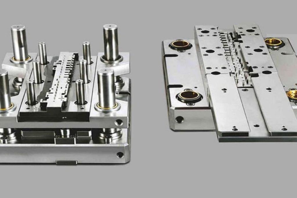
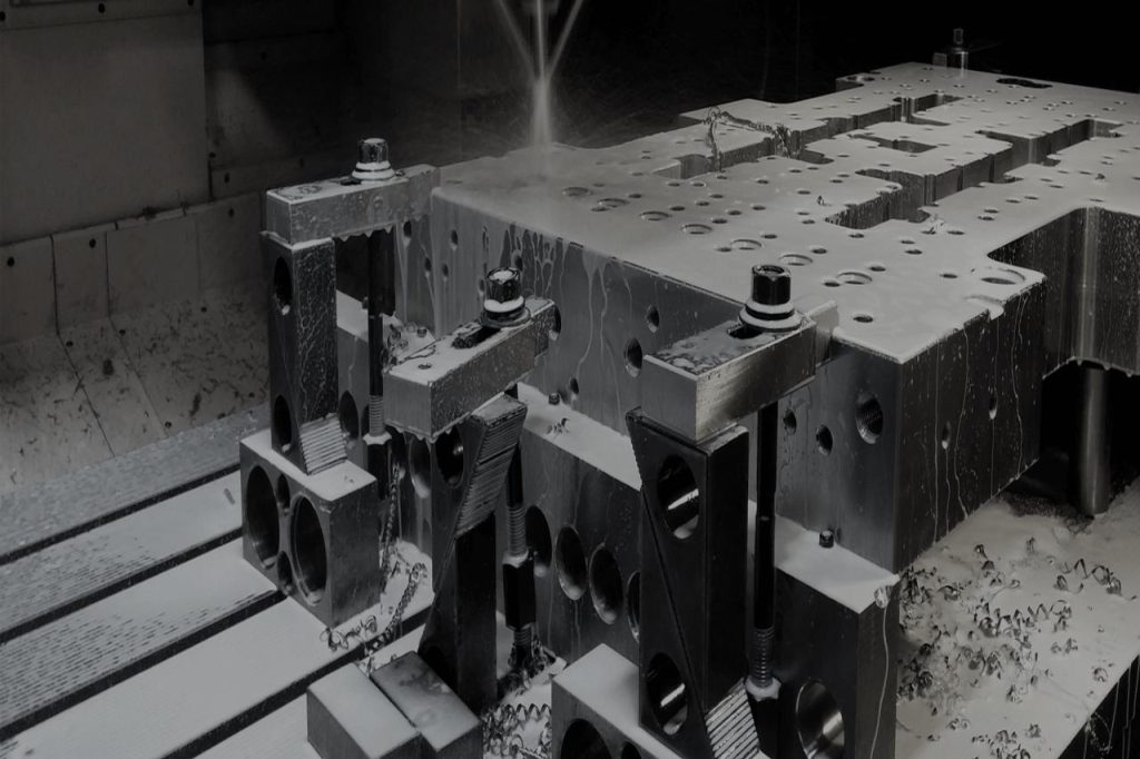
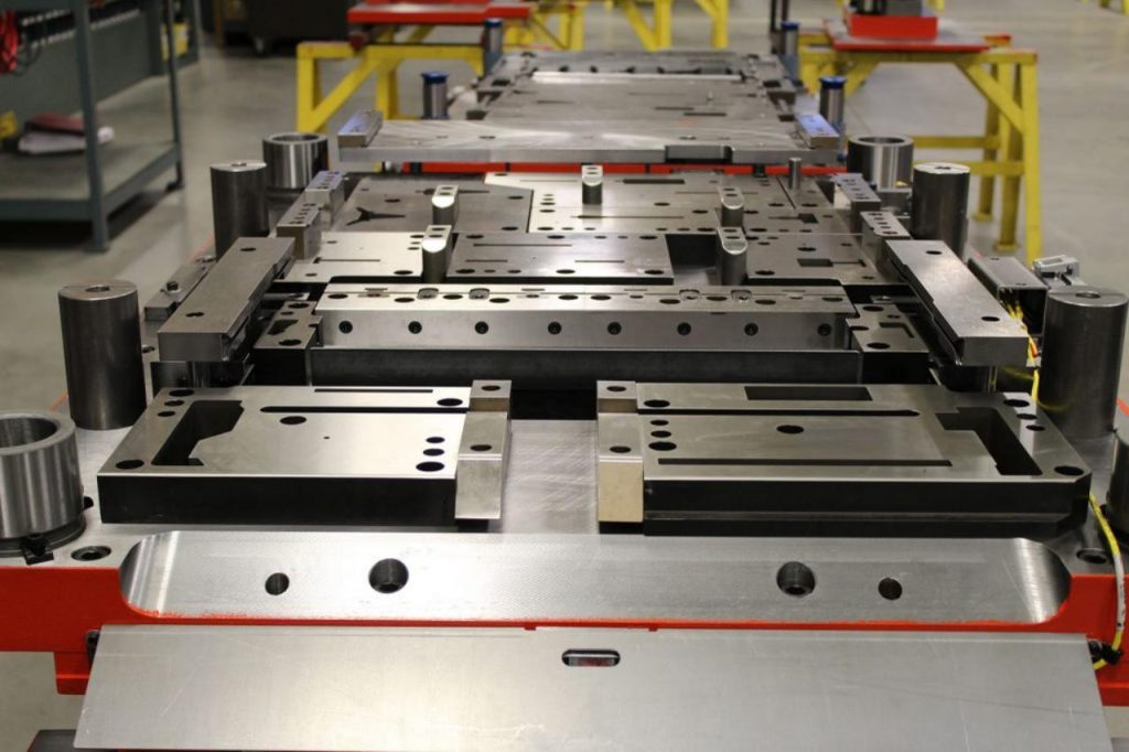
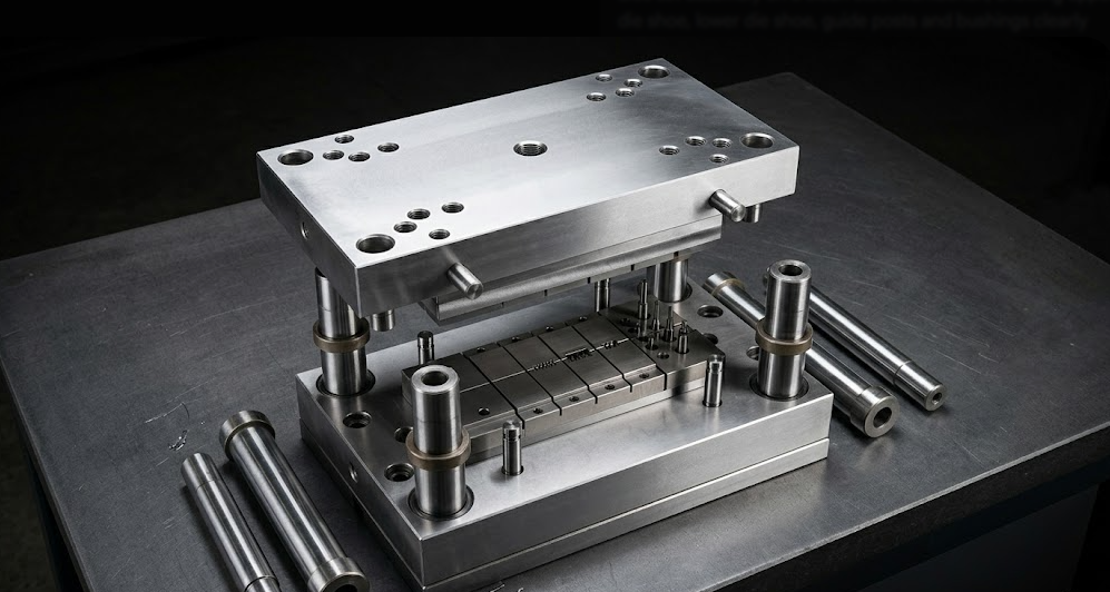
The die base is not merely a supporting structure; it is the foundation for maintaining the alignment, stability, and efficient operation of the entire stamping system. If the die base wears out too quickly, other components of the die will be affected—guide rails will loosen, precision will decrease, burrs will increase, and maintenance costs will rise. In mass production, such failures are costly, reducing production efficiency and shortening die life. Therefore, surface condition, material selection, heat treatment, and finishing processes all affect the die base’s wear resistance. If the surface is too rough, friction will increase, and damage will spread more quickly. If the surface is too soft, the die base will undergo geometric deformation under load. Improper finishing can cause even high-quality steel to perform poorly in actual production. Therefore, surface finishing optimization is needed to improve wear resistance and extend service life. Inadequate Surface Treatment Leads to Die Base Wear The base wear is mainly caused by repeated contact between mating components. Uneven surface treatment leads to localized stress concentration, increasing friction and accelerating wear. Over time, this leads to misalignment and performance degradation. In high-load applications, the heat generated by friction further exacerbates this process, leading to microscopic material deformation. As the surface deteriorates, the stability of the contact area decreases, leading to performance instability during stamping cycles. This progressive degradation underscores the importance of a uniform surface finish in die base machining. Surface defects, including machining marks and microscratches, can serve as initiation points for fatigue cracks. During high-cycle stamping operations, these defects propagate and compromise structural integrity. Therefore, controlling surface quality in die base machining is crucial for long-term reliability. Furthermore, cyclic stress amplifies these micro-defects, causing cracks to propagate beneath the surface. Once cracks form, this damage is difficult to detect until it affects product performance. Die Base Material Selection: The Foundation of Wear Resistance Material selection is critical in die base manufacturing. Tool steels and alloy steels must possess the hardness required for wear resistance while maintaining sufficient toughness to absorb impact. An optimal balance between hardness and toughness effectively prevents excessive wear and brittle fracture. The selection of appropriate materials also depends on the specific application environment, including load intensity, throughput, and operating conditions. Engineers must carefully evaluate these factors to ensure the die base operates reliably under actual operating conditions while avoiding unnecessary cost increases. Heat Treatment and Dimensional Stability Heat treatment can improve material properties but may introduce deformation. To ensure dimensional accuracy, subsequent finishing processes, such as grinding, are required. This ensures the mold base maintains its geometry under operating stresses. Furthermore, stress relief treatments can be used to minimize internal stresses that could lead to deformation during use. By combining appropriate heat treatment with precision finishing, mold base manufacturing can achieve both mechanical strength and geometric stability. Die Base Surface Finishing Techniques: Grinding, Polishing, and Control Grinding is the most critical finishing process in mold-based manufacturing. It ensures the flatness, parallelism, and controllable surface roughness of die bases. These factors directly affect load distribution and wear resistance. Furthermore, precision grinding enables micron-level control, which is crucial for high-precision mold systems. By achieving consistent surface quality, manufacturers can reduce friction and improve the mold base’s overall performance in demanding applications. In addition, while polishing improves surface smoothness, over-polishing can reduce lubricant retention. Therefore, a balance of surface texture is required. In mold-based manufacturing, functional finishing prioritizes performance over appearance. Therefore, engineers typically strive to achieve an optimal surface roughness range that balances low friction and effective lubrication. This balance ensures efficient die operation and durability over extended production cycles. CNC Precision and Workflow Integration CNC machining parameters—including cutting speed, feed rate, and toolpath—affect the final surface finish. Improper parameter control can lead to residual stress and surface defects, reducing wear resistance. Advanced CNC systems precisely control machining variables, enabling manufacturers to achieve consistent surface quality. By optimizing these parameters, die machining can significantly improve surface integrity and performance. Simultaneously, the sequence of machining, heat treatment, and finishing needs to be optimized. In specialized die machining, finishing is typically performed after heat treatment to ensure final dimensional accuracy and stability. By standardizing processes, manufacturers can minimize variability and ensure reliable die performance. Optimized Surface Treatment Processes Enhance Die Life By combining high-quality materials such as tool steel or pre-hardened alloys with advanced surface treatment processes (grinding, polishing, and surface coating), friction can be minimized, microcracks prevented, and the operational reliability of stamping dies improved. In addition, precision CNC machining, controlled lubrication, and regular inspections ensure that each mold base maintains dimensional accuracy, functional stability, and wear resistance throughout the extended production cycle.

Precision Stamping Die 1-2
Chaoyang blog

Precision Stamping Die Surface Finishing Guide: Reducing Burrs and Wear

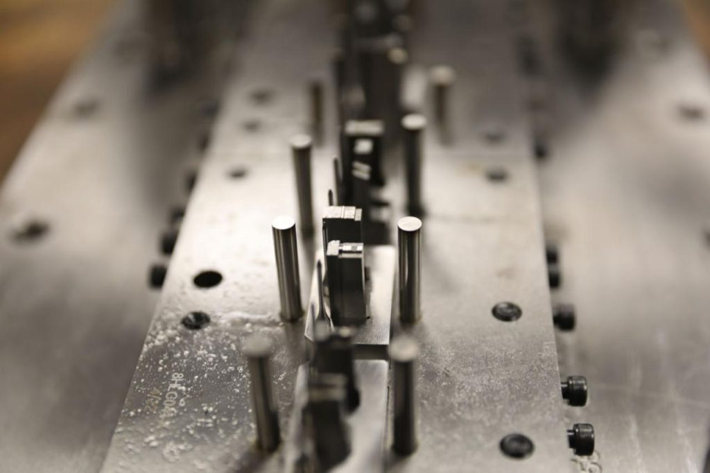
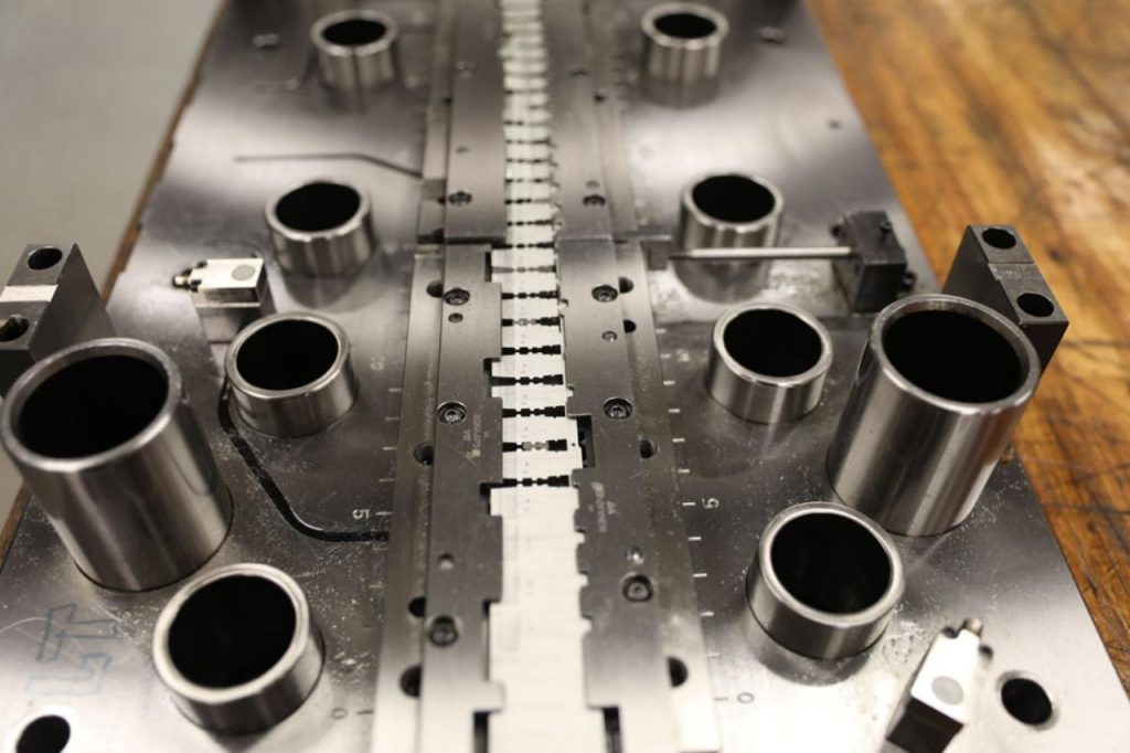
In the field of precision stamping, surface finish directly determines burr height, cutting edge quality, and die service life. By properly managing surface finish, you can effectively reduce scrap rates, minimize the frequency of regrinding, and extend die longevity; conversely, if neglected, every aspect—from part tolerances to press uptime—will suffer negative consequences. Therefore, we offer practical, engineering-based professional advice on surface finishing for precision stamping dies, helping your production line achieve smoother, more durable, and more cost-effective operations by minimizing burrs and wear. Surface Finish of Precision Stamping Die and Its Impact on Burrs and Wear The surface finish of a precision stamping die directly dictates how the material flows and fractures during the shearing process. A cutting edge with a superior finish minimizes irregular fracture zones and significantly reduces burr formation, whereas a poorly finished edge leads to inconsistent cut quality and excessive burring. It is essential to strictly control the interplay between surface roughness, edge sharpness, and material deformation to ensure consistent stamping performance. In actual Precision Stamping die manufacturing, surface finish also influences frictional behavior at the contact interface. When a die surface is excessively rough, it increases resistance during the material separation process, leading to heat accumulation and accelerated die wear. Conversely, an overly polished surface may compromise lubricant retention capabilities, thereby adversely affecting long-term performance. Surface Roughness, Edge Geometry, and Burr Control A low surface roughness (Ra 0.2–0.6 µm) on the shear face facilitates a clean, crisp cut, while a controlled micro-chamfer enhances cutting edge durability. Simultaneously, bearing surfaces require a delicate balance between smoothness and lubricant retention to minimize friction and wear. Furthermore, the geometry of the cutting edge plays a pivotal role in determining the distribution of stress during the cutting operation. A carefully designed micro-radius or micro-chamfer serves to prevent localized stress concentrations—conditions that frequently lead to micro-chipping of the cutting edge. In the processing of high-volume stamping dies, even minute deviations in the cutting edge treatment can lead to cumulative defects, such as burr formation and dimensional inaccuracies. Therefore, maintaining consistency in the cutting-edge geometry across all cutting components is critical for ensuring the repeatability of processing performance and minimizing the need for secondary finishing operations. The Impact of Material Selection and Heat Treatment on the Surface Properties of Precision Stamping Die Material selection plays a decisive role in the durability of stamping dies. Cold-work tool steels—such as D2 (SKD11)—offer excellent wear resistance, while powder metallurgy steels provide superior toughness and a more uniform carbide distribution. Furthermore, engineers select appropriate materials based heavily on specific application conditions, including the type of material they stamp, the production volume, and the required precision. For instance, stamping high-strength steels requires materials with exceptional toughness to resist cracking, whereas processing abrasive materials demands higher wear resistance. By aligning material selection with operational requirements, manufacturers can significantly reduce failure rates in precision stamping die applications and enhance the overall performance of the dies.  Machining and Grinding Processes for Ensuring the Surface Integrity of Precision Stamping Die Efficient stamping die processing necessitates a comprehensive workflow ranging from rough machining to fine grinding. Minimizing clamping errors and maintaining datum consistency are key to achieving high-precision machining results. Additionally, the machining sequence must be meticulously planned to mitigate the accumulation of residual stress and prevent deformation. The use of high-quality cutting tools, optimized cutting parameters, and stable fixturing systems ensures consistent machining accuracy. In high-precision applications, even minor deviations during the machining process can lead to alignment issues during assembly, ultimately compromising the die’s performance. Consequently, adopting a systematic machining strategy is essential for producing reliable precision stamping dies. Grinding and Edge Treatment Techniques The use of fine abrasives for grinding, combined with controlled cooling, helps prevent thermal damage. Furthermore, micro-chamfer designs and consistent edge treatments can significantly reduce chipping and extend die life. Beyond standard grinding operations, advanced finishing techniques—such as superfinishing or lapping—can be employed to further enhance surface quality. These methods help eliminate microscopic defects and improve the consistency of the cutting edges. The proper use of coolant during the grinding process is also critical, as overheating can alter material properties and reduce hardness. By integrating precision grinding and cutting-edge treatment techniques, manufacturers can achieve exceptional surface integrity and long-term durability in stamping die applications. Process Control, Lubrication, and Press Optimization Appropriate die clearance and alignment are essential for minimizing burr formation. Incorrect clearance in stamping dies can lead to excessive rollover or premature wear. Furthermore, maintaining stable stamping parameters ensures consistent production conditions; variations in these parameters can result in unstable cutting performance and increased tool stress. Regular calibration and monitoring of stamping equipment are vital for sustaining optimal performance. By controlling these variables, manufacturers can significantly reduce defects and enhance the processing efficiency of precision stamping dies. Achieving Long-Term Excellence Through Surface Finishing The performance of precision stamping dies is not determined by a single factor, but rather stems from the meticulous integration of various elements—including material selection, die machining, surface finishing, and operational control. To effectively minimize burrs and wear, a systematic strategy must be adopted that spans every stage: from controlling machining precision and applying coating technologies to optimizing process workflows and managing the entire product lifecycle. Crucially, achieving sustained success in precision stamping die applications demands an unwavering commitment to excellence in every detail at every stage. From achieving the appropriate surface roughness and cutting-edge geometry to selecting suitable heat treatment processes and applying advanced surface coating technologies, every decision exerts a critical influence on the overall stability and durability of the die.

Tooling Die Set(1)
Chaoyang blog

Tooling Die Set Material Selection: SKD11, SUJ2, Tool Steel & Pre-Hardened Steel Options

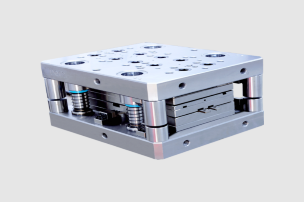
In precision manufacturing, the performance and durability of a tooling die set depend largely on the materials used in its manufacture. A well-designed tooling die set ensures consistent dimensional accuracy, stable production cycles, and a longer service life in high-volume production environments. Conversely, choosing unsuitable materials can lead to premature wear, cracking, or excessive maintenance costs. From an engineering perspective, die machining must balance several key factors, including hardness, wear resistance, toughness, and machinability. Each different material, such as SKD11, SUJ2, conventional tool steel, or pre-hardened steel, has a unique combination of these properties. Therefore, engineers must carefully evaluate the production environment, stamping pressure, and cycle frequency before determining the most suitable material. Commonly Used Materials in Tooling Die Set Manufacturing Manufacturers typically produce Tooling Die Sets using a range of specialized steels designed to withstand extremely high mechanical stresses and repeated operating cycles. The most commonly used materials include general-purpose tool steels such as SKD11, SUJ2, H13, and A2, as well as pre-hardened steels designed to increase machining speed and reduce heat-treatment requirements. Each of these materials plays a specific role in die machining. For example, SKD11 is widely known for its excellent wear resistance, making it suitable for cutting edges and high-friction surfaces. SUJ2, with its excellent hardness and fatigue resistance, is ideal for precision guiding components. Meanwhile, tool steels such as H13 combine strength and toughness, making them excellent for applications subjected to impact or thermal stress. On the other hand, pre-hardened steels offer significant advantages in processing efficiency and production costs. Because suppliers provide these materials in a partially hardened state, manufacturers can shorten production cycles and reduce the risk of deformation during die manufacturing. A Key Material Choice for Tooling Die Set Manufacturing SKD11 is a high-carbon, high-chromium cold work die steel, one of the most commonly used materials for manufacturing die components due to its excellent hardness and wear resistance. SKD11 exhibits excellent durability in high-friction or repetitive cutting operations. In actual die manufacturing, manufacturers often use SKD11 to manufacture components such as punches, cutting dies, and trimming tools. After proper heat treatment, the material can reach a hardness of HRC 60 or higher, maintaining a sharp cutting edge even after prolonged production operation. Another advantage of SKD11 is its excellent dimensional stability during heat treatment. This characteristic helps maintain tight tolerances in precision manufacturing environments. However, due to its high carbide concentration, SKD11 is relatively difficult to machine. Therefore, machining SKD11 parts for mold assemblies typically requires advanced CNC machining and EDM. SUJ2 Precision Mold Components SUJ2 is a high-carbon, chromium-bearing steel widely used in mold assemblies and is especially suitable for components requiring excellent hardness and fatigue resistance. Although initially developed for bearing applications, its excellent mechanical properties also make it suitable for certain mold components subjected to repetitive mechanical stresses. In tooling die set machining, SUJ2 is commonly used to manufacture guide pins, bushings, ejector pins, and locating components. These parts require smooth surfaces, high hardness, and excellent wear resistance to ensure precise positioning within the tooling die set. One of the main advantages of SUJ2 is its ability to achieve extremely high hardness after heat treatment while maintaining a good surface finish. This allows engineers to produce highly polished parts, thereby reducing friction and improving the operational stability of the tooling die set. However, manufacturers generally do not use SUJ2 steel for heavy-duty cutting edges or applications that require high impact strength because its toughness is lower than that of some tool steels. Tool Steel Options for High-Strength Mold Applications Tool steel remains a core material for mold components, possessing excellent properties such as hardness, toughness, and thermal stability. Engineers use H13, A2, and S7 as the most widely used tool steels, and they design each one for different operating conditions. H13 tool steel is particularly suitable for applications with high temperatures or repeated impact loads. In tooling die set machining, manufacturers often use H13 to manufacture mold bases, forming dies, and components that must withstand thermal stress. Its excellent resistance to thermal cracking and thermal fatigue makes it ideal for harsh industrial environments. A2 tool steel combines good wear resistance and machinability, making it suitable for general mold parts. Engineers recognize S7 tool steel for its excellent impact resistance, which makes it suitable for applications that experience sudden impacts or high punching pressure. By carefully selecting the appropriate tool steel, manufacturers can significantly improve the reliability and service life of mold assemblies while reducing maintenance needs and production downtime. Pre-hardened Steel and Machining Tooling Die Sets Pre-hardened steel has become an increasingly popular material choice in die manufacturing, especially where production efficiency and cost control are critical. Unlike traditional tool steels that require extensive heat treatment after machining, pre-hardened steel is supplied in a partially hardened state. This characteristic simplifies the die-machining process, reducing the number of manufacturing steps required to achieve the desired mechanical properties. Because the material is already hardened, manufacturers can perform CNC machining and grinding without concern for significant dimensional deformation during heat treatment. Pre-hardened steel is commonly used in die bases, support plates, and other structural components in tooling die sets. While their hardness may not be as high as SKD11 or other high-performance tool steels, they are sufficient to meet the strength and durability requirements of many applications. Tooling Die Set Machining and Surface Treatment Technologies In addition to material selection, the performance of tooling die sets is highly dependent on appropriate manufacturing processes and surface treatment technologies. Advanced tooling die set machining technologies, including CNC machining, wire EDM, precision grinding, and vacuum heat treatment, ensure that die components achieve the required dimensional accuracy and mechanical strength. Surface treatments such as nitriding, PVD coating, and hard chrome plating further enhance the durability of mold components by improving wear resistance and reducing friction. These processes form a protective layer, extending the service life of mold parts operating under high stress conditions. By combining suitable materials with advanced processing techniques, manufacturers can optimize the performance and

Stamping Dies(1)
Chaoyang blog

What Is the Difference Between Progressive, Compound and Single Stamping Dies?

From automotive brackets to electronic connectors, countless precision metal parts rely on stamping dies for stable and reliable production. However, choosing the right die structure is no easy task. Manufacturers must assess factors such as production volume, part complexity, material properties, and die investment before determining the most suitable stamping die processing method. Among the many die options, three basic types dominate industrial production: single stamping dies, compound dies, and progressive dies. Each design follows different working principles and offers advantages in terms of production efficiency, precision, and flexibility. Types of Stamping Dies and Their Manufacturing Characteristics Single-stamping dies are one of the most traditional and straightforward die solutions in metal stamping. In this type of die, only one operation is performed per stamping stroke, such as blanking, bending, or punching. A sheet metal or blank is placed inside the die, the press applies pressure, and the operation is completed in a stamping cycle. This stamping die processing method is particularly suitable for large parts, thick materials, or small-batch production. Because each process is performed independently, engineers can precisely control the forming pressure and adjust parameters to accommodate different material properties. Therefore, single-stroke dies are often used to produce large structural parts, heavy brackets, and prototype parts. Another advantage of this type of die is its relatively low cost. Compared to more complex die systems, single-stroke dies are simpler to design and have shorter manufacturing cycles. Furthermore, maintenance and repair are easier due to the fewer components in the die structure. However, single-stroke dies have limitations in terms of production efficiency. Because each operation must be completed individually, manufacturers typically require multiple dies or additional processing steps to produce complex parts. Therefore, while this type of die offers flexibility and reliability, it may not be suitable for high-volume production environments. Compound Stamping Dies Compound stamping dies combine multiple operations into a single stamping stroke. Unlike single-stroke dies, which can only perform one operation at a time, compound stamping dies can perform two or more stamping functions simultaneously, such as blanking and punching. In compound stamping, the workpiece remains stationary while the die performs multiple operations in a single stroke. This configuration significantly improves production efficiency by enabling multiple manufacturing steps to be completed concurrently. Furthermore, because compound dies form parts simultaneously, the machined parts maintain very precise positional relationships. Compound stamping dies are widely used in industries requiring precision flat parts, such as electrical components, gaskets, and metal seals. The ability of compound dies to maintain strict dimensional consistency between internal holes and external contours makes them particularly important in precision stamping applications. Despite these advantages, compound dies are more complex to design and manufacture than single-stroke dies. The die must carefully coordinate multiple punches and dies to ensure even pressure distribution during stamping. Progressive Stamping Dies and Their Advantages in Mass Production Progressive stamping dies are among the most advanced and efficient die solutions in modern mass production. In this stamping die system, a continuous strip of metal is fed into multiple stations within the die. Each station performs a specific operation, such as punching, bending, or forming, while the strip of metal advances within the die with each stamping stroke. This stamping die processing method allows manufacturers to produce finished parts through multiple consecutive operations without removing the workpiece from the die system. As the metal strip moves forward, each station progressively processes the material until the final part is formed and separates from the metal strip. Progressive stamping die is widely used to produce small- to medium-sized metal parts, such as connectors, clips, terminals, and electronic components. Because multiple processes are completed within a single die, production speeds can reach extremely high levels, making progressive stamping dies ideal for mass production. Key Differences Between Progressive, Compound, and Single Stamping Dies First, single stamping dies perform only one operation per stamping stroke. They are flexible and simple, suitable for small-batch production or large parts requiring high forming forces. Second, compound dies can complete multiple processes simultaneously in a single stroke. This allows manufacturers to maintain excellent positioning accuracy across the various features of the stamped part while increasing efficiency. Third, progressive stamping dies form the part step by step through a series of stations, with the metal strip advancing through the die to form the part ultimately. This system has the highest production efficiency and is widely used for the mass production of precision metal parts. From a stamping die processing perspective, the choice of die type mainly depends on production volume, part complexity, and die budget. Manufacturers must carefully evaluate these factors to determine the most cost-effective solution. Choosing the Right Die Design Each die type has its specific application in the stamping industry. Single stamping dies are simple and flexible, suitable for large parts or small-batch production. Compound dies complete multiple processes in a single stroke while maintaining high dimensional accuracy, thus improving production efficiency. Progressive stamping dies integrate multiple processing stages into a continuous production flow, making them the best solution for mass production. By carefully analyzing production requirements and material properties, the most suitable stamping die design for the project can be selected.

Chaoyang blog

Stamping solutions suitable for precision dies: easily adaptable to any project

From electronics, automotive, and aerospace to medical devices, manufacturing industries place extremely high demands on metal components, including exceptional precision, repeatability, and reliability. As product complexity and quality requirements continue to increase, manufacturers must rely on precision dies that provide high performance, consistent dimensional accuracy, and long-term operational stability. These dies are crucial for achieving rapid production cycles, maintaining component consistency, reducing scrap, and minimizing downtime. Chaoyang combines a CAD/CAM design platform with simulation-based die optimization and high-precision machining to deliver precision metal-stamping die solutions that consistently meet customer needs. The Technological Capabilities Behind High-Quality Precision Dies Reliable stamping projects begin with optimized precision die design. Chaoyang uses platforms such as SolidWorks and integrates CAD/CAM and simulation software to optimize die structures prior to production. By simulating forming, metal flow, and stress distribution in a digital environment, our engineers can identify potential problems such as cracking, wrinkling, thinning, or deformation early in the design process. This pre-design approach allows teams to fully fine-tune die geometry, guiding systems, and material selection before machining, significantly reducing costly trial-and-error. By applying simulation-driven design, we achieve superior forming accuracy throughout the production cycle, while improving die durability and operational efficiency. Therefore, our precision metal stamping die solutions are meticulously designed to reliably handle complex geometries and material properties, making them suitable for high-volume production of electronics, automotive, and aerospace components. Precision Machining Technology Ensuring High-Performance Dies After the design phase, precision machining ensures the accuracy and lifespan of precision stamping dies. Chaoyang employs a variety of high-precision machining technologies, including JG grinding, PG grinding, CNC machining centers, wire EDM, and precision surface grinding. These processes work together to achieve micron-level dimensional tolerances, ensuring precise alignment and consistent forming results during stamping. For example, JG grinding ensures ultra-high precision hole positioning for guide pins and bushings. In contrast, PG grinding enables the complex contours required for complex parts. Wire EDM (Electrical Discharge Machining) can cut intricate parts from difficult-to-machine metals, maintaining tight tolerances and eliminating heat-affected zones. CNC machining enables efficient, iterative modifications, while precision surface grinding delivers superior flatness and surface finish. The integration of these machining technologies ensures that precision metal stamping dies maintain performance stability while withstanding high-stress stamping operations. Material Selection Strategy for Manufacturing Durable Precision Metal Stamping Dies The materials used in precision dies determine their durability, wear resistance, and ability to maintain dimensional accuracy during high-volume stamping. Chaoyang carefully selects materials based on application scenarios, including cemented carbides, advanced ceramics, powder-metallurgy materials, and traditional tool steels. Cemented carbide exhibits excellent wear resistance under high-speed repetitive operations. At the same time, ceramics demonstrate superior hardness and stability under thermal and mechanical stress. Powder metallurgy materials combine toughness and precision, making them ideal for complex die shapes. At the same time, traditional tool steel remains a cost-effective solution for less demanding applications. By customizing material selection to meet project requirements, Chaoyang ensures that every precision metal stamping die delivers consistent stamping results, reduces maintenance frequency, and extends die life. Flexible Precision Stamping Solutions for a Variety of Manufacturing Projects Different projects require stamping dies capable of handling materials with varying thicknesses and mechanical properties. Chaoyang designs precision dies that efficiently process metals from 0.1 mm to 2.0 mm thick, providing exceptional versatility across numerous industries. This capability allows manufacturers to apply the same die design principles across multiple product lines, from ultra-thin electronic contacts to thicker automotive and appliance components. By optimizing die geometry, guide systems, and clearance settings, we maintain consistent precision regardless of sheet thickness. Therefore, our precision stamping solutions are suitable for both small-scale prototyping and high-volume production, making them highly adaptable to project-specific requirements and rapid product development cycles. Continuous Stamping Die Solutions for Complex Production For high-volume, complex processes, continuous precision dies can complete multiple forming, stamping, and bending steps in a single cycle. Chaoyang uses a SolidWorks-based CAD/CAM workflow to design progressive dies, ensuring precise alignment between stamping stages. This multi-stage process reduces material handling and production cycles while minimizing dimensional deviations between production batches. Each stage is meticulously calibrated to avoid misalignment, overstress, or surface defects. Progressive dies can also manufacture multiple part features simultaneously, increasing efficiency without sacrificing precision. By employing these precision metal stamping dies, manufacturers can achieve faster production cycles, lower scrap rates, and consistent output quality, even for complex or multifunctional components. Complete Die Assembly and Trial Run Services High-performance, precision dies require careful assembly and validation through trial runs before mass production. Chaoyang provides end-to-end die assembly and trial run services, ensuring all dies are ready for immediate production upon delivery. Our engineers conduct multiple trial runs to verify dimensional accuracy, material flow, guide system alignment, and forming performance. We fine-tune each die to optimize its performance, ensuring consistent results under full-scale production conditions. This process reduces setup time, ensures repeatable quality, and minimizes manufacturer downtime. By combining design, machining, and thorough validation, Chaoyang delivers fully production-ready precision metal stamping die solutions that support customer efficiency and operational reliability from day one. Providing High-Quality Precision Dies Chaoyang’s expertise in precision stamping dies offers comprehensive, flexible, and reliable solutions to meet project needs of varying complexity. By integrating advanced CAD/CAM design, simulation-based optimization, precision machining technology, and rigorous quality control, our precision metal stamping dies consistently deliver superior precision, durability, and repeatable performance. From handling various material types and thicknesses to providing progressive die solutions for multi-stage processes, Chaoyang ensures that every die is fully ready for immediate production. We offer end-to-end service, including die assembly, commissioning, and inspection, minimizing downtime, maximizing operational efficiency, and guaranteeing consistent product quality.

precision machining
Chaoyang blog

Can precision machining meet the precision requirements in aerospace and automotive parts manufacturing?

In aerospace and automotive parts manufacturing, precision requirements are extremely high. These components must operate reliably under extreme temperatures, high pressures, vibrations, and continuous mechanical stress. Even micron-level deviations can affect safety, performance, and service life. Can modern precision machining technology truly meet such stringent standards? Chaoyang believes the answer lies in materials science, advanced equipment configurations, rigorous process flows, and strict quality control. We provide comprehensive precision machining services, offering manufacturing solutions for complex industrial applications that combine dimensional accuracy, structural strength, and repeatable consistency. The Importance of Precision Machining for Aerospace and Automotive Parts Precision machining is the cornerstone of modern aerospace and automotive engineering. From engine housings and transmission components to structural supports and molds, every part must meet stringent tolerance and performance requirements. Therefore, qualified precision machining manufacturers must integrate advanced equipment, stable materials, and rigorous process control to ensure that each component operates exactly as designed. In addition to dimensional accuracy, manufacturers must also guarantee surface finish, geometric tolerances, and assembly compatibility to prevent cumulative errors during final integration. The Role of Precision Machining in High-Performance Component Manufacturing Precision machining ensures that critical aerospace and automotive components maintain dimensional stability even under high mechanical loads. For example, turbine housings, braking components, and fuel system components require tight tolerances to guarantee efficiency and safety. Through controlled CNC milling, turning, and multi-axis machining, specialized precision machining services ensure repeatable results for both prototyping and mass production. Furthermore, consistent machining accuracy minimizes vibration, friction, and wear, thereby extending the lifespan of finished products. Such high reliability can only be achieved through careful management of machining parameters, tool calibration, and environmental control. Material Selection and Durability Material integrity directly impacts machining performance and the long-term stability of components. Chaoyang uses robust and durable materials such as cemented carbide, ceramics, and tool steel to manufacture molds and critical tooling. These materials possess excellent wear resistance and thermal stability, enabling molds to maintain dimensional accuracy under high-intensity use. In the aerospace and automotive manufacturing industries, repeated cycles and extreme conditions are common; selecting durable materials ensures long-term tolerance and stability. As a precision machining manufacturer, we prioritize not only machinability but also overall lifecycle performance, ensuring components maintain structural integrity throughout extended production processes. Micron-Level Precision and Industry Standards The aerospace and automotive industries typically require micron-level tolerances. Achieving such high precision necessitates not only advanced machinery but also systematic calibration, skilled technicians, and rigorous inspection processes. Through optimized workflows and stable environmental control within our workshops, our precision machining services consistently deliver parts that meet stringent engineering specifications. Furthermore, maintaining micron-level precision improves assembly alignment, reduces rework, and enhances the safety of the final product. When dimensional deviations are minimized during machining, downstream production processes become more efficient and predictable. How Does Chaoyang’s Precision Machining Capability Meet Industry Needs? At Chaoyang, we combine advanced equipment, an experienced engineering team, and a comprehensive quality management system to meet the precision machining requirements of aerospace and automotive customers. Our workshops are equipped with CNC milling, turning, EDM, drilling, wire EDM, and precision grinding capabilities. We are equipped with Moore JG grinders, WASINO PG grinders, and Sodick oil-based cutting machines, enabling us to handle complex geometries and maintain tight dimensional control. This advanced configuration shortens production cycles while ensuring consistent quality for high-volume, high-complexity projects. Advanced Equipment Configuration in the Precision Machining Shop Precision machining heavily relies on equipment stability and process flexibility. Our machining centers support multi-axis operation, reducing repositioning errors and improving geometric accuracy. By integrating milling, turning, EDM, and grinding into a coordinated workflow, we streamline production processes and reduce accumulated tolerances. As a result, customers in the aerospace and automotive industries can achieve faster lead times without compromising quality standards. CNC milling and turning are fundamental to the production of complex parts. Multi-axis machining enables the completion of complex contours and chamfering in a single setup, reducing alignment errors and improving repeatability. This integrated machining approach improves productivity and dimensional consistency. Furthermore, an automated tool monitoring system further stabilizes machining performance, ensuring long-term accuracy even during extended production runs. Electrical Discharge Machining, Wire EDM, and Precision Grinding Technologies Electrical discharge machining (EDM) and wire EDM are crucial for manufacturing precision parts from hardened materials. Our Sodick oil-based EDM machines enable precise cuts and minimize thermal deformation. At the same time, Moore JG and WASINO PG grinders provide exceptional surface finishes and tight tolerance control. Precision grinding ensures flatness and parallelism, critical for mold inserts and aerospace structural components. The combination of these technologies enhances our ability to meet stringent engineering specifications. Integrated Tooling and Fixture Solutions for Optimized Production In addition to component machining, our precision machining services include comprehensive tooling and fixture design. Custom fixtures stabilize parts during machining and inspection, reducing positioning errors and improving repeatability. Furthermore, dedicated inspection fixtures improve measurement efficiency during assembly verification. By designing and manufacturing fixtures in-house, we optimize alignment accuracy, reduce setup time, and improve overall operational efficiency. This integrated capability makes Chaoyang a manufacturer offering comprehensive precision-machining solutions. Quality Assurance and Inspection in Precision Machining Services Quality verification is central to aerospace and automotive production. Our quality assurance team uses Zeiss Coordinate Measuring Machines (CMMs), Trimos 2D height gauges, and Nikon measuring microscopes to verify micron-level tolerances. These tools enable detailed geometric analysis, surface inspection, and dimensional verification of complex components. Through standardized inspection processes, we ensure consistent quality across every production batch. When these devices work together, they ensure dimensional accuracy and stability throughout production. Precision Machining as a Key Capability in Precision Manufacturing Precision machining, through carefully selected materials, world-class equipment, rigorous process control, and traceable metrology, fully meets the precision requirements of aerospace and automotive component manufacturing. Chaoyang Company possesses advanced equipment, including Moore JG grinders, WASINO PG grinders, Sodick EDM platforms, and multi-axis CNC machining centers, along with tooling design and a comprehensive inspection infrastructure, enabling our precision machining services to deliver micron-level accuracy and long-term reliability.

Automotive Parts Precision Machining 1
Chaoyang blog

Automotive Parts Precision Machining: A comparison of 3D design and 2D design modeling capabilities

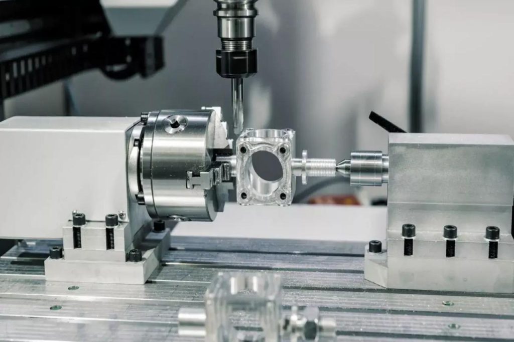
In the automotive parts precision machining, whether you are producing high-volume engine mounts, safety-critical suspension components, or small-batch prototype housings, the part modeling method used in the design phase determines the ease and reliability of subsequent precision machining. Both 3D modeling and 2D drafting during the design phase affect the precision of machining automotive parts. We will focus on practical results: tolerance control, programming complexity, CAM/CNC integration, inspection, delivery cycle, and cost. If you are responsible for part design, mold making, or production planning, this section will help you choose a modeling method that provides predictable accuracy and better production economics. Differences between 2D and 3D Design in Automotive Parts Precision Machining In the automotive parts precision machining, the modeling strategy directly determines programming efficiency, tolerance stability, and production reliability. Although 3D and 2D design methods are still widely used throughout the automotive supply chain, their impact on precision machining differs significantly. 2D design has supported precision machining for decades. In this approach, geometry is conveyed through orthographic and sectional views, along with detailed dimensions. For simple automotive parts such as brackets, gaskets, and drill blocks, 2D drawings remain practical and cost-effective. However, 2D designs require interpretation. Machinists and CAM programmers must mentally reconstruct spatial relationships before generating toolpaths. For complex tolerance chains, such as concentric holes or multi-plane datums, this conversion step introduces risk. In the precision-machining environment for automotive parts, as complexity increases, relying solely on 2D modeling can lead to longer setup times, more conservative fixture strategies, and greater reliance on operator experience. 3D Design Modeling Enhances Automotive Parts Precision Machining 3D modeling fundamentally changes how precision machining workflows operate. Solid models embed geometric relationships directly into the part structure. Features such as fillets, grooves, holes, and surfaces are defined parametrically, meaning changes propagate automatically while maintaining design intent. For automotive parts precision machining, 3D modeling provides: Clear spatial visualization Direct CAM data integration Associative tolerance definitions Reduced programming ambiguity Furthermore, Model-Based Definition (MBD) directly integrates geometric dimensions and tolerances (GD&T) into the digital model, enabling synchronization of machining and inspection workflows. Improved tolerance clarity leads to improved machining consistency. The Impact of 3D vs. 2D Machining on the Automotive Parts Precision Machining Performance Design methodology influences every variable in downstream manufacturing—from toolpath generation to inspection, fixture design, cost, and long-term scalability. In precision machining operations, CAM efficiency determines product quality and delivery speed. With 3D models, toolpaths can be calculated directly from the actual solid geometry. Operations such as roughing, finishing, contouring, and multi-axis machining can all be simulated in a virtual machining environment before production begins. This capability avoids collisions, optimizes cutting fits, ensures predictable cycle times, and reduces the need for iterative adjustments. In contrast, 2D-based workflows typically require intermediate 3D modeling before programming begins. This additional step increases development time and can lead to geometric interpretation errors. For automotive parts requiring strict control over fan-edge, contoured surfaces, or multi-faceted alignment, 3D-driven precision machining offers significant advantages. Fixture Design and Benchmarking Strategies Fixtures determine the repeatability of machining. In the precision machining of automotive parts, 3D modeling enables engineers to design fixtures and digitally verify them virtually. Accessibility to multi-axis machining can be pre-assessed, reducing the number of actual clamping operations required. Fewer setups yield measurable benefits: Reduced cumulative tolerance build-up Improved concentricity control Shorter production cycles Increased part consistency When machining based solely on 2D drawings, fixture engineers rely more on experience and manual interpretation of the layout. This may be sufficient for simple parts. However, for complex castings or housings, 3D data ensures precise alignment of reference points during machining. Final Recommendations The key to automotive parts precision machining lies in the clarity of design and the standardization of manufacturing processes. 3D design and modeling empower modern CAM, simulation, and metrology workflows, resulting in repeatable accuracy and shorter lead times. While 2D drawings still play a role in clarifying simple parts and contract terms, manufacturers and engineers should adopt relevant strategies: use 3D models for manufacturing-critical geometries, retain 2D models where budget allows, and unify benchmarking and verification methods for both models. This balanced approach can improve the quality of automotive parts, accelerate production, and deliver predictable performance.

precision machining capabilities(1)
Chaoyang blog

What precision machining capabilities should a reliable stamping die manufacturer possess?

A reliable stamping die manufacturer translates tight tolerances, complex geometries, and tight production schedules into predictable output, rather than scrambling to cope with unexpected situations. Chaoyang employs a system-level approach to die manufacturing: mature machining platforms, an experienced die workshop, and a process control system that integrates design, CAM, and metrology into a repeatable process. Chaoyang’s precision machining capabilities encompass jig grinding, contour grinding, surface grinding, wire EDM, CNC machining, EDM, milling, and drilling, all equipped with well-staffed tool shops and state-of-the-art machinery. Core Precision Machining Capabilities a Stamping Die Manufacturer Must Master Jig grinding is one of the most precision-intensive processes in die manufacturing. It directly determines the geometric accuracy of critical components such as punches, inserts, and guide elements. A reliable stamping die manufacturer must be equipped with high-end jig grinding machines capable of achieving micron-level tolerances. At Chaoyang, our Moore jig grinding machines ensure extremely high concentricity and positional accuracy. This technology ensures perfect alignment of die components during assembly, minimizing wear and extending die life. Without advanced jig grinding technology, consistent part quality cannot be guaranteed in high-speed stamping operations. Contour and Surface Grinding Capabilities of Manufacturers Complex contours require advanced contour-grinding technology. Professional stamping die manufacturers must possess contour grinding systems capable of handling complex radii, compound curves, and precision angles. Our WASINO contour grinders achieve precise forming, meeting stringent customer specifications. Simultaneously, surface grinding ensures flatness, parallelism, and surface finish—factors crucial in stamping die machining, as a consistent pressure distribution must be maintained on the contact surfaces. Wire EDM and Electrical Discharge Machining Capabilities of Stamping Die Manufacturers Electrical Discharge Machining (EDM) plays a central role in modern stamping die machining. Reliable stamping die manufacturers must integrate wire EDM and countersunk EDM technologies to handle complex geometries and hardened materials. Wire EDM for Contour Precision Our Seibu waterline EDM machines offer exceptional cutting precision for hardened tool steels. Wire EDM enables the machining of complex internal contours, sharp angles, and high tolerances that are unattainable with conventional machining. The final machined edges are clean and sharp, requiring minimal secondary machining. Countersunk EDM for Complex Cavities Our Sodick oil-line EDM machines can machine deep cavities and special shapes with excellent surface finish and dimensional consistency. These machines are essential for producing inserts and formed parts that require extremely high structural integrity. The combination of these EDM capabilities ensures that Asahi can provide advanced stamping dies that meet the complex needs of industry. Advanced CNC Facilities for Stamping Die Manufacturer The excellence of precision machining is not just reflected in a single machine. A true stamping die manufacturer must integrate CNC systems, workflow optimization, and quality control into a complete production strategy. CNC machining is the cornerstone of modern die manufacturing. A reliable stamping die manufacturer must operate multi-axis CNC machining centers capable of high-speed, high-rigidity cutting. At Chaoyang, we utilize AWEA, AGMA, and Vision Wild CNC machining centers manufactured in Taiwan, providing the following services: Stable heavy-duty cutting performance High spindle accuracy Excellent thermal stability Efficient multi-faceted machining These machines are used to machine complex mold frames, templates, and structural components. By performing milling, drilling, and tapping operations within integrated machining centers, we reduce repositioning errors and improve production efficiency. Milling and Drilling Accuracy Advanced equipment is important, but fundamental machining techniques such as milling and drilling are also crucial. As a reliable stamping die manufacturer, we ensure: Precise hole positioning Correct alignment of guide pins and bushings Controlled wire quality Optimized cutting parameters to extend tool life During our precision machining processes, we emphasize process specifications and accurate programming. Every stamping die machining project follows proven machining strategies to prevent deformation and maintain dimensional accuracy. A Fully Equipped Tooling Shop and Production Coordination Machining capabilities alone do not determine reliability. A comprehensive tooling shop, backed by a highly skilled team of technicians, enables seamless integration across design, machining, and assembly. Our in-house tooling shop ensures immediate feedback between machining and assembly teams, reducing outsourcing delays, implementing quality control at every stage, and achieving shorter delivery times. Chaoyang streamlines workflows and accelerates delivery by integrating processes such as jig grinding, EDM, CNC machining, milling, and drilling into a coordinated system. This vertical integration allows us to maintain consistent product quality while meeting tight production cycles. Superior Precision Machining Capabilities A reliable stamping die manufacturer must demonstrate comprehensive die machining capabilities, including jig grinding, contour grinding, surface grinding, wire EDM, EDM forming, CNC machining, milling, and drilling. At our Chaoyang factory, we offer Moore jig grinders, WASINO contour grinders, Seibu water-line EDM machines, Sodick oil-line EDM systems, and Taiwanese-made AWEA, AGMA, and Vision Wild CNC machining centers, forming a complete, integrated production ecosystem. This infrastructure enables us to optimize workflows, shorten delivery times, and maintain uncompromising quality, thus becoming a reliable stamping die manufacturer.

CNC Precision Parts 1(1)
Chaoyang blog

CNC Precision Parts vs Traditional Precision Parts: Precision Comparison

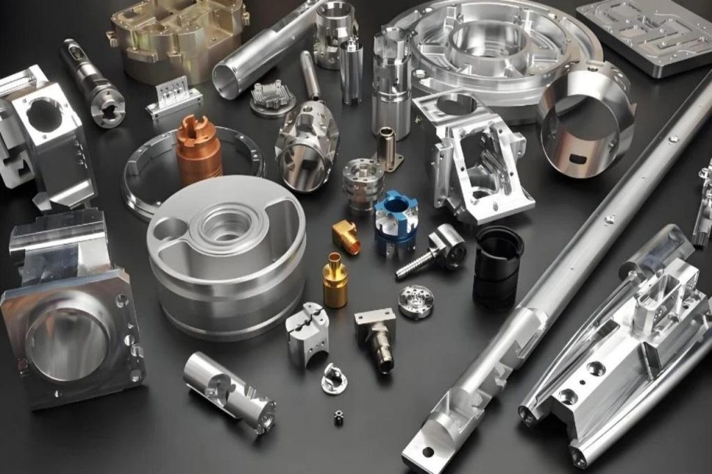
Our engineers are frequently asked whether CNC machining produces parts with superior performance compared to conventional methods. The real question is: “Which combination of processes, materials, inspection, and planning can meet your product’s required tolerances, surface finish, and repeatability at an acceptable cost and delivery time?” We will compare CNC precision parts and conventional precision parts from the perspective of all key attributes in production: dimensional accuracy, geometric control, surface quality, repeatability, throughput, material selection, process risk, and cost. Precision of CNC Precision Parts vs. Conventional Precision Parts Precision is not just about tight tolerances; it’s also about repeatability, geometric stability, and long-term functional performance. In parts manufacturing, CNC precision parts represent a data-driven, digitally controlled approach to achieving precision. Unlike conventional machining methods that heavily rely on operator experience, CNC systems operate through programmed toolpaths, closed-loop servo control, and automatic compensation systems. Today’s CNC machining centers integrate CAD/CAM programming, thermal compensation, high-resolution encoders, and real-time feedback loops. These technologies work together to reduce axis misalignment, spindle runout, and geometric error accumulation. Therefore, the dimensional tolerances of the CNC precision part is typically ±0.01 mm or less, depending on the application requirements. In contrast, traditional precision parts are usually produced using manual lathes, milling machines, coordinate grinders, and skilled manual finishing techniques. While these methods can produce high-precision individual parts, they rely more on process skill than on digital repeatability. Therefore, although traditional machining still has value in specific situations, CNC-based production methods offer greater consistency in medium to high-volume production. Dimensional Accuracy and Geometric Control of CNC Precision Parts Dimensional accuracy can be measured, but geometric accuracy determines functional success. CNC precision parts benefit from multi-axis machining capabilities, significantly reducing repositioning and reclamping errors. For example, five-axis CNC machining can complete the machining of complex geometries in a single setup, minimizing accumulated tolerances. Furthermore, CNC machine tools integrate online probes and automatic tool compensation correction functions. These features ensure consistency across different production batches and reduce reliance on manual adjustments. CNC machine tools can maintain production efficiency while controlling positional accuracy, flatness, perpendicularity, and concentricity within extremely high tolerances. Therefore, when comparing CNC precision parts with traditional precision parts, the key difference lies not only in achievable tolerances but also in the repeatable geometric control of hundreds or thousands of parts. Surface Finish and Functional Fit Surface quality directly affects sealing performance, wear resistance, and mechanical life. The CNC precision part achieves consistent surface finishes through optimized toolpaths, high-speed spindles, coated tools, and vibration control systems. Feed rate regulation and constant chip load programming further enhance surface integrity. For applications requiring tight-sealed interfaces, bearing journals, or sliding fits, CNC machining provides predictable Ra values ​​and uniform material removal patterns. Furthermore, advanced CAM software reduces toolpath marks and waviness height, improving surface smoothness without requiring excessive secondary finishing. Traditional methods, such as hand polishing or grinding, can achieve ultra-fine surface finishes under specific conditions. However, these methods are labor-intensive and difficult to scale up. Comparison of Operating and Economic Costs of CNC Precision Parts vs. Conventional Precision Parts Material selection typically determines the complexity of machining. CNC precision parts are suitable for a wide range of materials, including aluminum alloys, stainless steel, tool steel, copper alloys, titanium, and nickel-based alloys. Through programmable feed rates, adaptive cutting strategies, and coolant optimization, CNC can effectively control work hardening and heat buildup in difficult-to-machine materials. Furthermore, CNC platforms can be seamlessly integrated with electrical discharge machining (EDM) and precision grinding processes to handle internal cavities, deep ribs, and micro-features. Conventional machining methods can also process similar materials, but efficiency and repeatability may be affected when machining high-strength or heat-resistant alloys. Operator fatigue and manual adjustments further increase the variability in machining difficult-to-machine materials. Therefore, CNC precision parts offer significant technological advantages for industries with high material complexity and stringent tolerance requirements, such as aerospace, medical devices, automotive, and energy systems. Production Efficiency, Scalability, and Cost Structure Cost analysis must consider the economic benefits throughout the entire lifecycle, not just the machining time per piece. While CNC machining requires significant capital investment, it offers exceptional cost-effectiveness in medium- to high-volume production. This advantage lies in reduced manual labor, automated tool changes, shorter machining cycles, and minimized scrap rates. Software-based program modifications allow for rapid iteration without redesigning physical fixtures. This flexibility significantly enhances scalability. Traditional precision machining methods appear more cost-effective for single prototypes or very small batch production, especially when setup time is much longer than programming time. When to Choose CNC Precision Parts vs. Traditional Precision Parts The choice between CNC and traditional machining methods depends on application requirements. CNC precision parts should be chosen when: Tight tolerances must be maintained during mass production. Complex geometries require multi-axis machining. Materials include titanium, Inconel alloys, or hardened tool steel. Process traceability and digital quality records are mandatory. Large-scale production is a strategic priority. Traditional precision methods should be considered when: Creating a model with the simplest geometry and the simplest prototype. Performing specialized manual finishing operations. For emergency repairs or minor modifications. In many practical applications, a hybrid approach is the best choice. CNC machining efficiently generates the basic geometry, while selective conventional finishing ensures a superior surface finish when needed.

Die Components Fabrication 2
Chaoyang blog

Die Components Fabrication Design Guide: Key Principles for Mold Matching

Chaoyang’s manufacturing philosophy is simple: design manufacturable, repeatable, and cost-effective die components before any part enters the production workshop. By integrating Design for Manufacturing (DFM) principles into the design phase of mold component manufacturing, we can make strategic decisions early on regarding part structure, material selection, tolerances, and tooling—reducing unnecessary complexity, shortening development cycles, and ensuring production yields. Our collaborative DFM approach, and how we utilize advanced 3D modeling and simulation technologies (UG, Pro-E, CAD, CAE, CAM), along with machining and process control, delivers precision mold components that meet the stringent tolerance requirements of stamping manufacturers, ensuring that the tolerances of key die components fabrication features are within ±1 μm. Die Components Fabrication Design for Superior Mold Matching In die component fabrication, Chaoyang employs a collaborative Design for Manufacturing (DFM) approach for mold matching. We do not design components in isolation, but simultaneously evaluate part geometry, structural logic, material properties, tolerance feasibility, and production scalability. Through DFM analysis, we assess factors such as stress concentration, heat treatment deformation risk, machining ease, and long-term wear performance. This proactive approach ensures that mold components are not only theoretically sound but also capable of large-scale production in practical applications. Therefore, we reduce redesign cycles, shorten delivery cycles, and improve mold matching efficiency during assembly and trial molding. 3D Modeling and Simulation in Die Components Fabrication Design Digital validation is the cornerstone of our die component fabrication strategy. We utilize advanced software platforms, including UG, PRO-E, CAD, CAE, and CAM, to build fully parametric 3D models to simulate actual manufacturing and forming conditions. These tools enable us to detect potential problems before production begins, such as interference fits, insufficient material flow, springback deformation, or insufficient forming radius. CAE analysis provides in-depth insights into stress distribution and deformation behavior, which is particularly important when forming stainless steel, copper alloys, high-carbon steel, titanium, or Inconel alloys. Furthermore, CAM integration ensures that toolpaths are optimized for accuracy and repeatability. This digital-first approach enhances mold matching performance. It provides precise alignment of upper and lower die components during production trials, reducing setup time and stabilizing stamping performance in high-volume production. Material Selection Strategy in Die Components Fabrication Material selection plays a decisive role in die matching stability and die life. In die part manufacturing, inappropriate material combinations can lead to premature wear, chipping, scratches, or deformation under load. Chaoyang evaluates material compatibility based on stamping application requirements, expected throughput, forming forces, and surface finish requirements. For example: High-carbon tool steel offers excellent wear resistance and is suitable for long-term stamping. Powder metallurgy alloys offer superior microstructure uniformity. Carbide inserts enhance the performance of stainless steel in abrasive forming. Special alloys are selected when stamping titanium or Inconel alloy parts. Furthermore, we consider the coefficient of thermal expansion to ensure dimensional stability of the material at different temperatures. Material selection is always closely integrated with tolerance planning and heat treatment sequence. Precision Engineering and Manufacturing Capabilities in Die Components Fabrication Precision machining determines the functional quality of die components. Chaoyang Company possesses core capabilities covering the entire engineering process of stamping dies, ensuring unparalleled dimensional control and surface finish. Our available machining technologies include: Jig grinding for achieving ultra-fine contour accuracy. Contour grinding for precision machining of complex shapes CNC milling for structural geometry machining Wire EDM for machining complex internal contours Precision surface grinding for controlling flatness and parallelism. These technologies enable us to control the tolerances of punches, dies, and guide systems to within ±1μm in a controlled production environment. By combining machining process planning with DFM-based design, we avoid excessive post-machining corrections and minimize manual assembly during die assembly. Optimizing Die Fit through Precision Assembly and Verification Die fit is the link between design theory and production practice. Even perfectly machined die components require systematic alignment and assembly strategies to ensure optimal performance. Chaoyang employs a structured assembly process, supplemented by coordinate measuring systems and precision alignment tools. Each guide post, bushing, punch holder, and die insert is inspected before final integration to ensure compliance with design specifications. Furthermore, we simulate stamping conditions during trial molding to verify load distribution, clearance control, and peel balance. For stainless steel and high-strength alloys, we fine-tune clearances to prevent burr formation and excessive tool wear. Simultaneously, we monitor thermal expansion behavior during continuous operation, especially when molding titanium and Inconel alloys. By predicting material springback and die deformation, we can improve die matching accuracy early in the validation phase. Die Components Fabrication Through Precision Manufacturing Processes Chaoyang uses a collaborative DFM (Design for Manufacturing) approach to ensure that the design of each die component not only focuses on dimensional accuracy but also on manufacturability, durability, and long-term production stability. By utilizing advanced 3D modeling platforms such as UG, PRO-E, CAD, CAE, and CAM, we are able to identify and eliminate potential risks in the early design stages of die components fabrication. Meanwhile, we possess comprehensive machining capabilities, including JG, PG, CNC milling, wire EDM, and precision surface grinding, enabling us to consistently achieve tolerances of ±1μm. This combination of digital verification and precision mold engineering ensures superior mold-fitting performance across a wide range of materials, from stainless steel and copper alloys to titanium and Inconel.

Scroll to Top