Automotive stamping tolerances are not tight because of an industry rule. They are tight where the part’s function demands it — and relaxed where it does not. A terminal’s contact surface, a bracket’s locating hole, and a cosmetic outer edge carry very different limits on the same drawing. Understanding where the tightness comes from changes which features you chase and which you can safely leave loose.
You must then translate these requirements into a process that can produce and verify the part consistently. Material variation, springback, die wear, and measurement methods all influence dimensional results. So engineers and buyers should check each factor when reviewing a drawing or evaluating a supplier.
Where Automotive Stamping Tolerances Come From
The pressure does not start at the stamping press. It starts at the assembly line and the function of the finished part. Why automotive parts pull specific features in tight, and why the same part can carry both very tight and very loose limits, both trace to that starting point.
Why Do Automotive Parts Demand Tighter Tolerances Than General Stamping?
Why are automotive stamping tolerances so tight? The best answer comes from what the part has to do, not from a typical value. Three mechanics drive the tightness:
- Automated assembly. Robots and feeders cannot adjust a part that does not fit. A locating hole that drifts can stall a line or jam a fixture.
- Function stacking. A connector terminal’s contact force, insertion force, and retention all depend on dimensions that must hold across millions of pieces.
- Failure cost. A drifted feature shows up as a quality issue inside the vehicle — far more expensive than a rework at the press.
The drawing sets how tight each feature gets. It usually references the customer’s own standards or an internal specification for critical dimensions. Automotive stamping tolerance standards may cover dimensions that carry no individual callout. Critical features often need individually defined dimensional or geometric tolerances, based on their functional requirements and the customer’s specifications.
Which Automotive Features Set Stamping Tolerances?
The useful way to read an automotive stamping drawing is stamping tolerance by feature. Each feature earns its limit from its role:
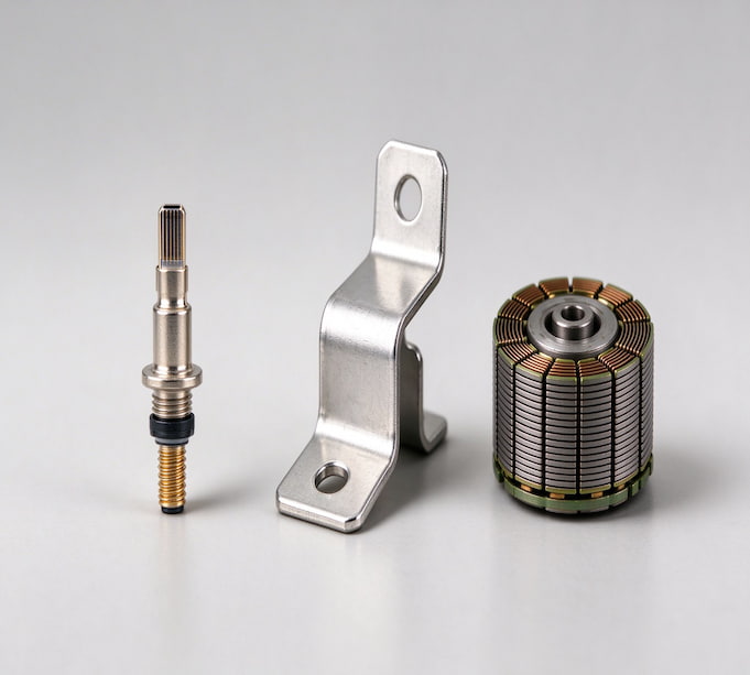
- Automotive connector terminal stamping tolerance — contact areas, locking lances, and mating surfaces carry the tightest limits, because they define electrical and mechanical function.
- Automotive sheet metal stamping tolerances — locating holes and critical assembly interfaces stay tight, while general profile and bend positions can relax.
- Motor lamination stamping tolerance — tooth profiles, bore concentricity, and lamination consistency define motor performance, so they carry strict limits.
- Cosmetic edges, clearance holes, and non-functional surfaces — these can run at general tolerances without hurting assembly or function.
So the skill is deciding which bucket a feature belongs to. Over-specifying a clearance hole buys nothing. Under-specifying a terminal contact face invites field failures.
What Turns Automotive Stamping Tolerances into a Process Plan?
Between the drawing and the shipped part sits a chain: functional requirement → critical feature → process variation → measurement and process control. A drawing states where the part should be; the die, the press behavior, and the inspection method decide whether it gets there. Every link either wins the tolerance or loses it.
Why Does Springback Move the Part After Forming?
Every bent or drawn feature springs back a little when the press releases. In short, formed sheet metal partially recovers its shape after forming ends. So it can shift bend angles, formed heights, and other dimensions away from their intended values. High-strength steel stamping can bring significant springback, but the effect depends on grade, thickness, geometry, and forming conditions. Die designers compensate with over-bending or coining steps. Yet the compensation must match the actual grade and thickness.
Springback is not a fixed number you can look up. It shifts with material grade, sheet thickness, bend radius, and tooling gap. A die tuned for one coil can drift when the next coil behaves differently. For a deeper reference on how advanced high-strength steels behave during forming, the advanced high-strength steel stamping guidelines cover the material side in detail.
Why Do Parts Drift After the First Thousand Strokes?
Tolerances on day one are not the same as tolerances at stroke 200,000. Punch edges wear, die clearance grows, and burr height climbs. So every buyer should ask early: how does die wear affect stamping tolerance? The answer decides whether a supplier plans for wear or waits for it.
Where wear concentrates, hard carbide inserts and replaceable punches are common choices. Shops often schedule maintenance by stroke count, depending on the application, material abrasiveness, and feature criticality. In short, a supplier who treats dies as disposable until parts fail is betting your line against wear.
Which Measurements Count on a CMM Report?
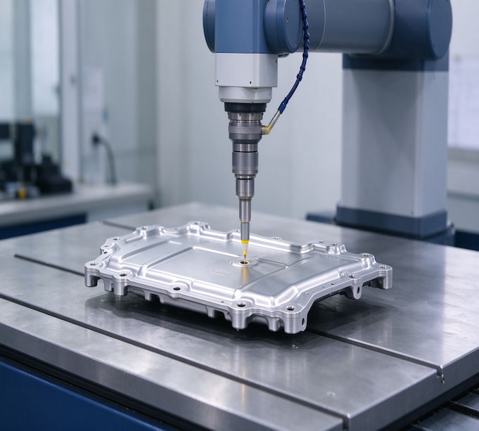
If you cannot measure a tolerance, treat it as a guess. Automotive prints normally pair each critical feature with a verification method. CMM covers positions and profiles where the feature justifies it; air gauges or micrometers cover bores; optical projectors cover contours. Position, flatness, roundness, and repeatability are different indicators. Mixing them up produces reports that look fine and prove nothing.
The check that matters most: does the measurement reference the same datum as the drawing? The inspection setup should follow the datum scheme on the drawing. If the reference or the feature evaluation differs from the specified method, the report may not show whether the part meets the requirements. So confirm the method suits the tolerance, and check the reported results against the drawing’s acceptance criteria.
What Should You Confirm Before Specifying Automotive Stamping Tolerances?
Before you finalize a drawing or select a shop, run four checks. This is also what to look for in a stamping supplier in practice:
- Which features actually affect assembly or function? Tighten those, relax everything else.
- Is each critical tolerance paired with a named measurement method and the same datum as the drawing?
- Has the tooling plan absorbed springback and planned for wear — not just quoted the press speed?
- Does the shop hold the die precision and inspection capability the tolerance needs, or is it hoping the part lands?
Where the tolerance demands real die accuracy — ground locating surfaces, wire-cut inserts, controlled clearances — the machine list tells you quickly whether a shop can support it. In that case, precision grinding and wire EDM can hold locating and bore features in the micron range, depending on the feature, material, and part geometry. A look at precision stamping capabilities shows what those requirements look like on actual equipment.
Automotive stamping tolerances are tight where function demands it, and the rest of the part can breathe. The next step sits on your side of the table. Identify the critical features on your drawing. Pin the measurement datum to each one. Then ask the supplier how they verify stability across a production run, not just on the first piece. Those three actions turn a tight number from something to fear into something you can hold.