
Precision die design is not a single event. It is a structured process that begins with reviewing a customer drawing and ends after the die has been validated through a trial run.
Each phase builds on the last. If one step is skipped, problems can appear quickly, including dimensional drift, premature tool wear, and rising scrap rates in production.
For engineers and procurement teams evaluating precision stamping dies, understanding this process helps set realistic expectations and reduces costly surprises.
Precision Die Design Starts with the Customer Drawing
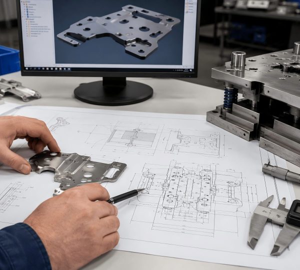
Every precision die design project starts with the customer drawing.
Before any design work begins, the engineering team reviews several key details:
- Part geometry
- Material type and thickness
- Critical dimensions
- Tolerance requirements
- Stamping direction
- Estimated production volume
Material choice affects the entire approach. Stainless steel, copper alloy, and high-tensile steel all behave differently under forming loads.
Production volume also shapes early decisions. A die intended for 500,000 cycles requires different steel grades and component configurations than one built for a short run.
Any ambiguity in the drawing gets resolved with the customer before design moves forward.
DFM Analysis Before Die Design
Design for Manufacturability, or DFM, analysis happens before formal die design starts.
This step identifies forming risks while changes are still inexpensive. The engineering team checks whether the part geometry is achievable through progressive stamping without modification.
Common issues found during DFM include:
- Insufficient bend radii
- Features too close to the blank edge
- Holes inside forming zones
- Springback that makes flat sections non-flat
- Strip layout problems
- Station planning risks
If the strip layout cannot accommodate the geometry efficiently, minor drawing revisions may be suggested with the customer’s approval.
Catching these problems in DFM costs almost nothing. Catching them during a trial run is expensive.
CAD Design and Process Planning
Once DFM is complete, the team moves into CAD-based die design.
This stage usually covers:
- Strip layout
- Station arrangement
- Forming sequence
- Pilot positioning
- Punch and die clearance
- Full die structure planning
Station sequence determines which operations happen in which order. These may include piercing, blanking, bending, drawing, and coining.
The sequence must follow a logical form. Holes punched too early may distort during later bending. Pilots must be placed where the strip is stable.
SolidWorks is often used to model the complete die assembly. This allows interference checks and clearance verification before any steel is ordered.
Machining and Component Manufacturing
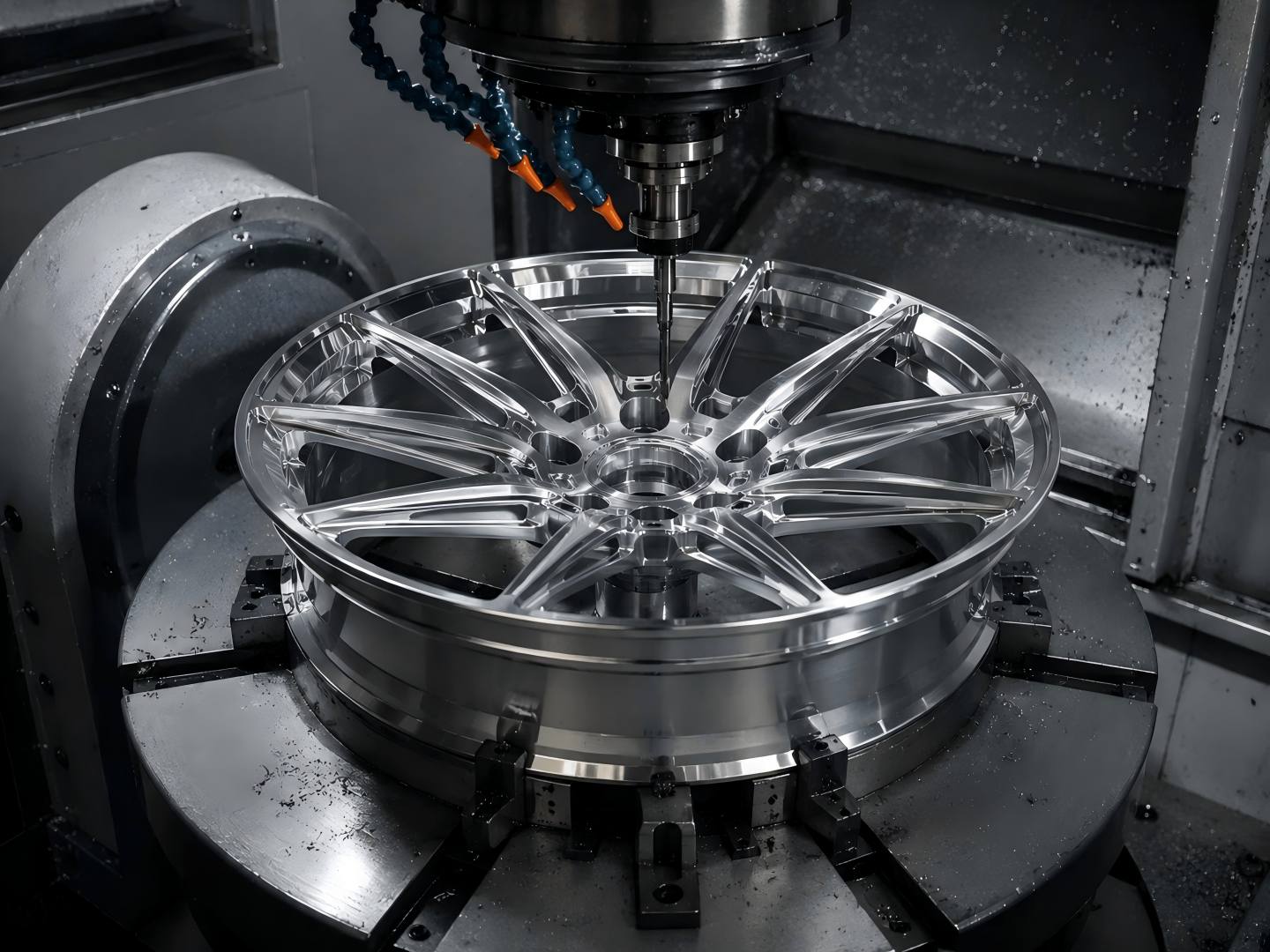
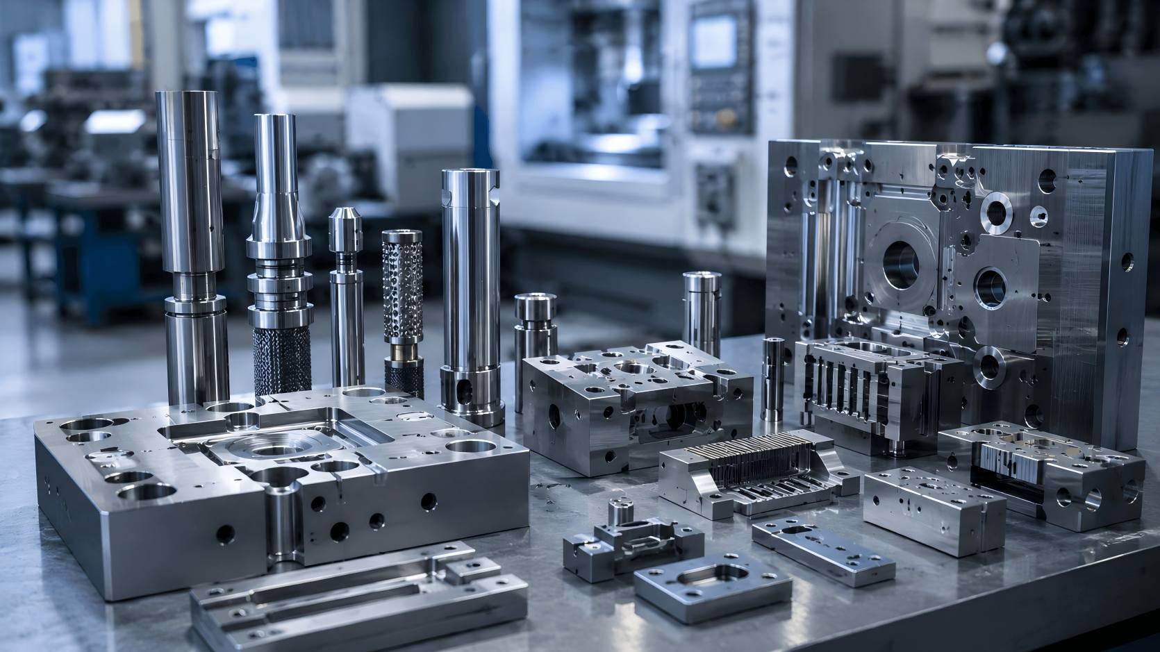
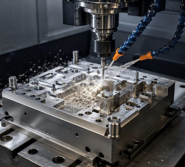
Die components are manufactured through CNC machining, wire EDM, grinding, and heat treatment.
Each process has a different role:
- CNC machining removes material efficiently for rough profiles.
- Wire EDM handles tight features such as punch and die clearances, intricate contours, and fine slots measured in microns.
- Jig grinding and profile grinding bring critical surfaces to final dimensions.
- Heat treatment hardens tool steel to the required Rockwell hardness.
- Finish grinding restores geometry to the final tolerance after heat treatment.
Throughout machining, components are measured against design intent.
Common inspection tools include:
- CMM inspection
- Profile projectors
- Height gauges
- Micrometers and pin gauges
A punch ground 0.005mm outside clearance tolerance may seem minor. In a high-speed die, it can accelerate edge chipping and shorten tool life significantly.
Die Assembly and Trial Run
Assembly begins once all components pass inspection.
The main parts are fitted together according to the assembly drawing, including:
- Punches
- Die plates
- Inserts
- Guide pins
- Springs
- Strippers
Close attention is given to punch-to-die clearance, guide alignment, and stripper travel.
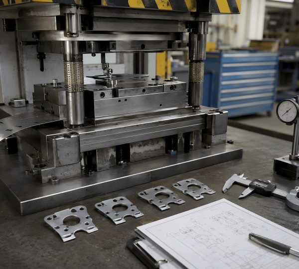
The first trial run uses the actual production material. The die is mounted in the press, and a short strip feeds through to produce initial samples.
Those samples are checked against the part drawing for:
- Dimensions
- Hole positions
- Bend angles
- Flatness
- Burr height
- Surface marks
- Cracking or material lifting
Adjustments are expected at this stage. Springback may pull a bend angle off slightly. A punch may need relief to reduce burr height.
The trial run continues until samples consistently meet drawing requirements. The die also needs to run cleanly, without burr problems, cracking, or unstable feeding.
What Affects Final Die Performance
Several factors affect final die performance:
- Tolerance control during machining
- Tool steel selection
- Surface finish on cutting edges and forming radii
- Punch and die clearance
- Heat treatment stability
- Maintenance planning
- Communication between buyer and manufacturer
Tool steel selection matters because high-wear areas may need carbide inserts or harder tool steel. This can extend maintenance intervals in high-volume applications.
Surface finish also affects part quality directly. A poorly finished radius can create drag marks and inconsistent part geometry.
Communication between buyer and manufacturer plays a practical role as well.
Buyers can reduce production risks by providing:
- Complete drawings
- Material specifications
- Expected production volume
- Press specifications
- Clear quality requirements
- Fast responses to DFM questions
A clear, precise die design process reduces rework, improves part consistency, and makes production more stable.
When drawing review, DFM, CAD design, machining, and trial run testing are handled properly, the die is easier to adjust, inspect, and maintain.
For buyers, the real value is not only a completed die but a tool that can produce accurate parts reliably in long-term production.