Chaoyang handles precision stamping die design through a structured engineering process that begins with product design review and DFM analysis, then moves into CAD/CAE/CAM modelling, tooling development, prototype validation, die testing, and long-term technical support. We connect each phase, so material, tolerance, and forming decisions carry through to final tooling.
Starting with Design Review and DFM Analysis for Precision Stamping Dies
Every project starts with a review of the customer’s drawings, samples, material specifications, tolerance requirements, production volume, and application environment. This gives the engineering team a clear picture of what the part needs to do and what forming challenges are likely.
Engineers then apply DFM (Design for Manufacturability) analysis to assess whether the part design is practical to produce within the required tolerances and target volume. The review typically covers:
- Part geometry and forming feasibility
- Material type and thickness
- Tolerance requirements
- Burr control and edge quality
- Cracking, deformation, or springback risks
- Expected production volume
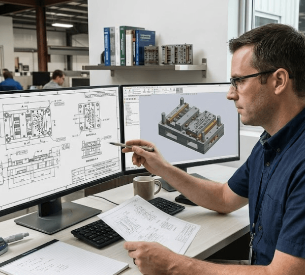
Precision Stamping Die Design: CAD, CAE, and CAM
With the DFM review complete, the engineer uses software platforms such as UG (Unigraphics) and PRO-E to develop the tooling geometry and layout. Strip ling team moves into die structure design. Engineers plan the layout and station sequencing during this phase to determine the most efficient sequence for blanking, punching, bending, and deep drawing.
CAD, CAE, and CAM each play a distinct role in this stage:
- CAD helps engineers build 3D models, die layouts, and detailed engineering drawings for all tooling components.
- CAE helps analyse forming risks, material flow, deformation behaviour, and springback before any physical tooling is produced.
- CAM prepares machining paths for CNC milling, wire cutting, and other tooling processes, translating the die design into precise manufacturing instructions.
Together, these tools reduce the gap between design intent and manufactured output.
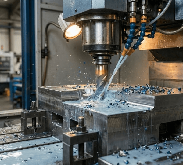
Tooling Development and Sample Validation in the Die Design Process
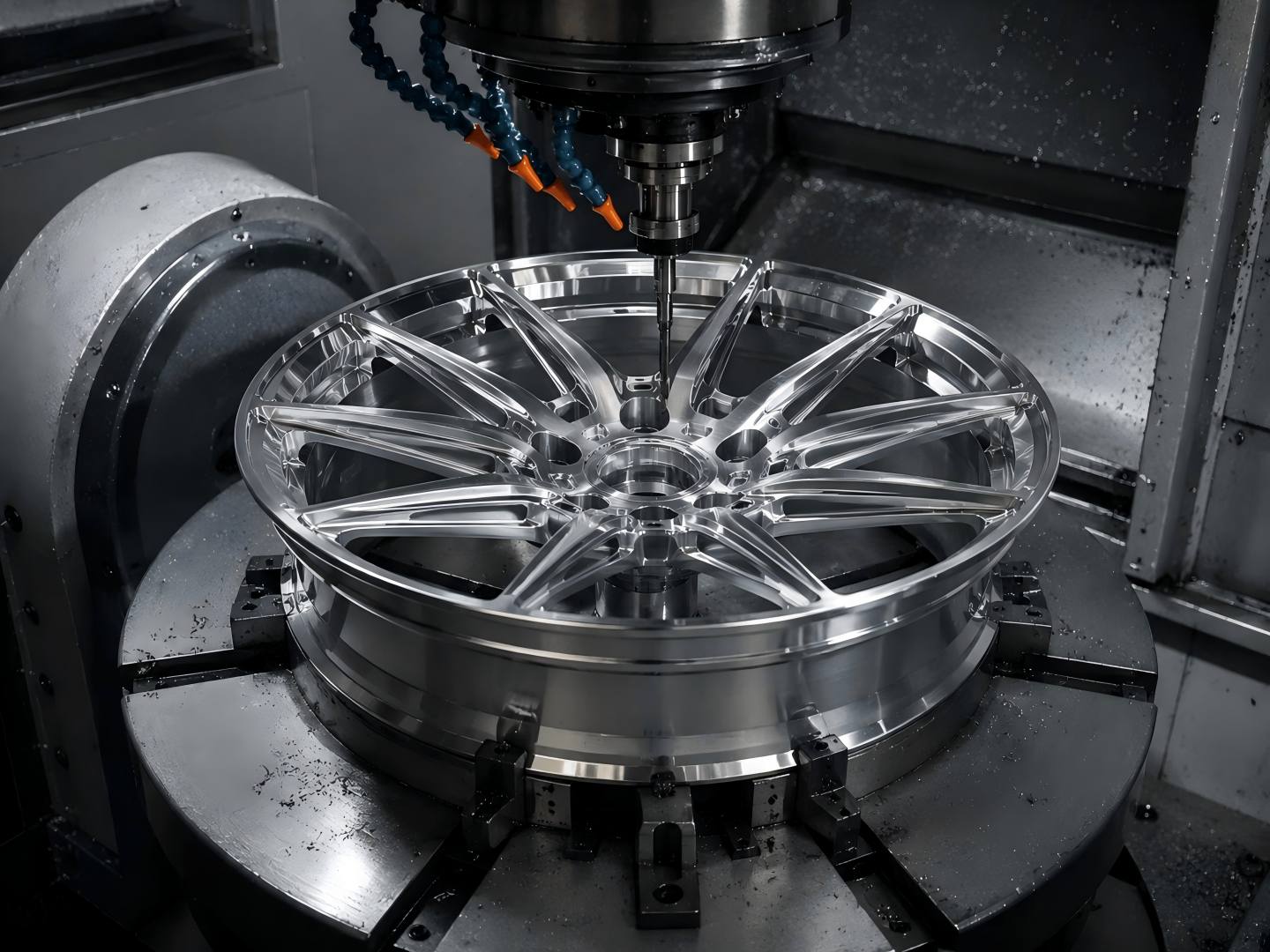
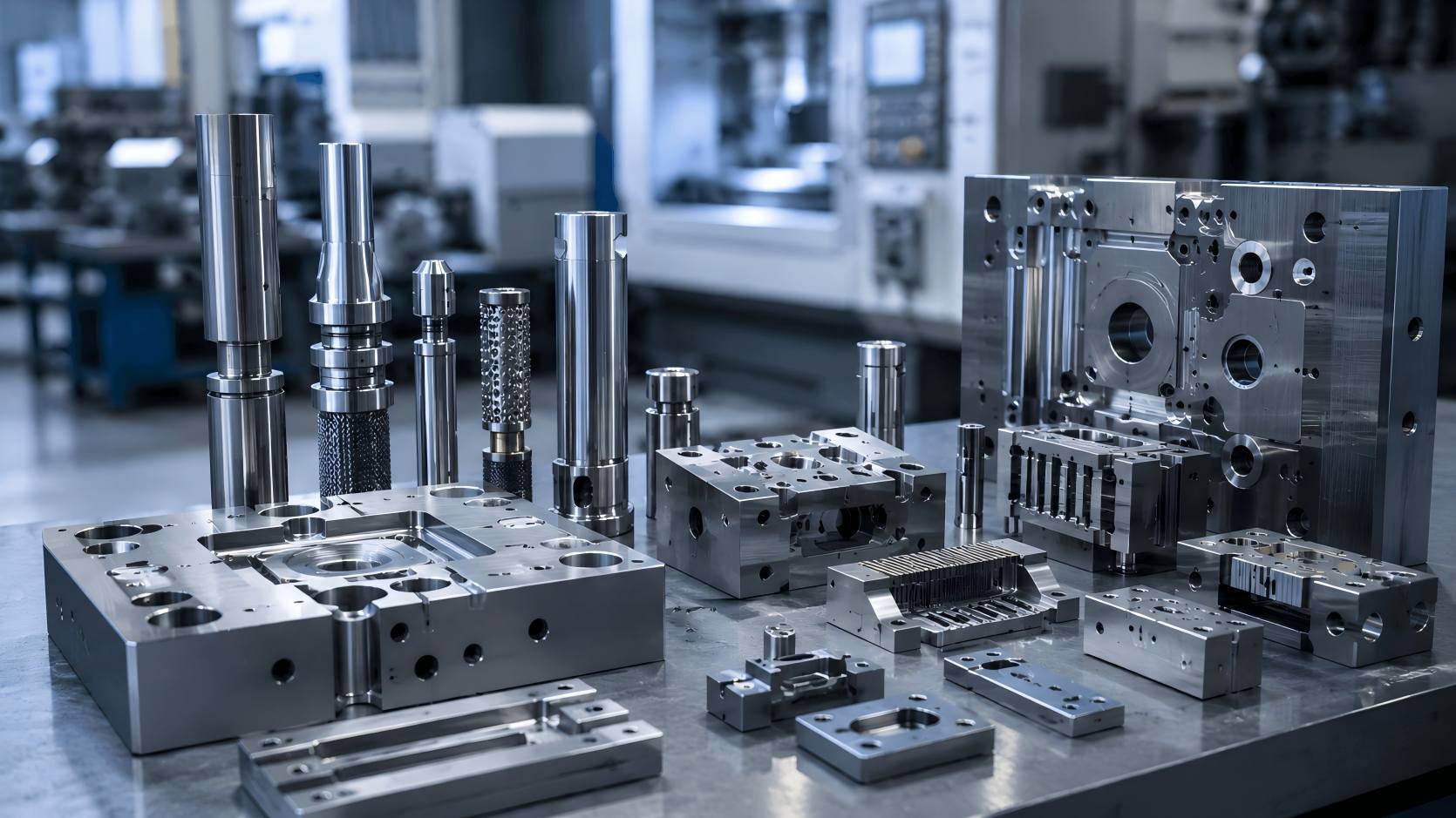
Once engineers finalise the mould design, they begin mould development. Engineers use wire cutting, CNC milling, and precision grinding to manufacture dies that meet dimensional tolerances.
When needed, engineers apply surface treatments such as TiCN and DLC coatings to improve wear resistance and extend die service life. For new part designs or complex geometries, soft dies or rapid prototyping methods are used to produce initial parts for validation. Once verified, hardened production dies are then manufactured.
Engineers inspect sample parts for dimensional accuracy, edge quality, and compliance with shape, fit, and function specifications. This validation step allows the team to confirm that the die operates as designed and to make targeted adjustments before proceeding to full-scale production.
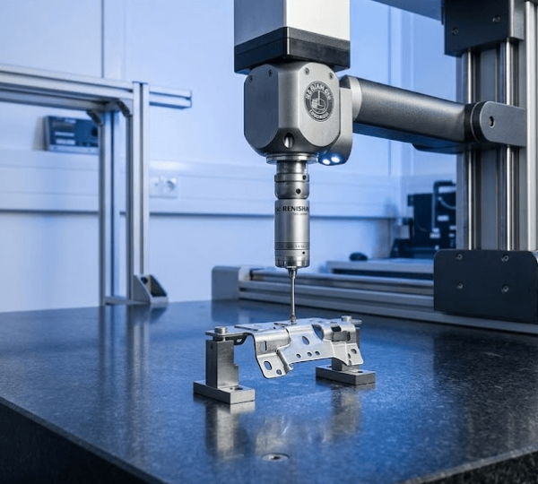
Die Testing and Process Validation Before Production
Before a die is approved for production, Chaoyang runs in-house stamping trials to verify process performance under realistic operating conditions. The die testing and process validation phase includes:
- Press trial and tonnage review
- Feed speed adjustment
- Lubrication testing
- Dimensional inspection with CMM
- Optical comparator checks
- Surface roughness measurement
- Sample performance reports
Engineers record dimensional conformance, surface condition, and process stability in process reports. These reports also serve as a reference baseline for tooling maintenance and future production runs.
Precision Stamping Die Design Process at a Glance
| Stage | Main focus | Key methods | Why it matters |
|---|---|---|---|
| Product review & DFM | Part feasibility, tolerances, and material behaviour | Drawing review, DFM analysis, Risk review | Finds design and production risks early |
| Die structure design | Tooling layout and forming sequence | CADCAECAMStrip layout | Improves tooling accuracy and production stability |
| Tooling & prototyping | Tool build and sample validation | CNC Wire cutting, Grinding, Soft tooling | Reduces trial-and-error before mass production |
| Die testing & validation | Production readiness | Press trials, CMM inspection, Process reports | Confirms performance before full production |
| Lifetime support | Long-term tooling performance | MaintenanceRegrindReplacementRecoating | Supports stable use after delivery |
Supporting Different Industry Requirements
Manufacturers rely on precision metal stamping tooling across many sectors, and each industry brings different requirements. Automotive and EV applications often require tight tolerances on structural or connector components and may involve advanced high-strength steels or lightweight alloys. Electronics and 5G parts typically involve small features, fine pitch dimensions, and strict surface finish requirements.
Aerospace and medical tooling projects carry additional documentation, traceability, and testing requirements. Consumer goods production often involves higher run volumes, where tool longevity and part-to-part consistency become the primary focus.
Chaoyang adapts its design engineering process to each sector and application by adjusting material selection, coating specifications, tolerance targets, and validation standards.
From Initial Design to Stable Production
A structured precision die design process reduces production risk, improves dimensional consistency, and shortens trials before full production. A defined sequence links DFM analysis, CAD modelling, tooling development, validation, and testing for more predictable results. Whether the work involves progressive stamping die design for high-volume runs or tooling development for complex part geometries, a clear engineering process is what connects the initial design to stable, repeatable production output.
