
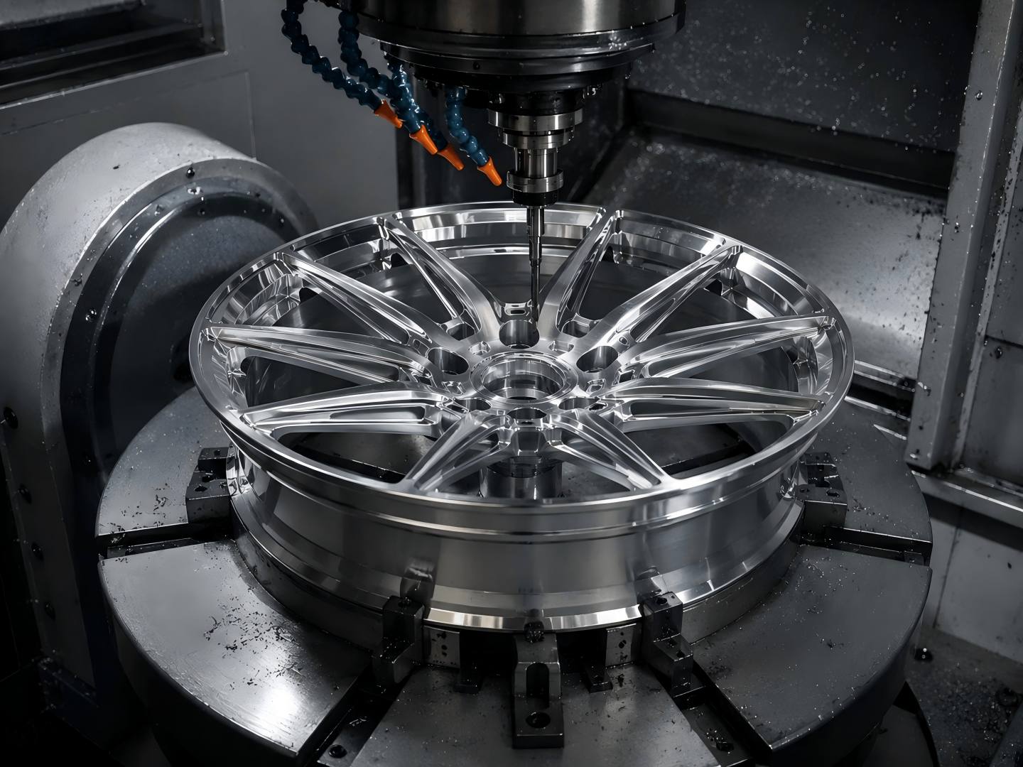
The wheel hub machining process directly affects bolt hole position, center bore accuracy, offset control, mounting surface flatness, bolt seat quality, and surface finish. For automotive components such as wheel hubs, each machining stage affects final assembly stability. One small error can compound throughout the rest of the process. Tight process control from blank inspection through final inspection helps reduce rework.
Key Accuracy Points in the Wheel Hub Machining Process
| Machining Area | Why It Matters |
|---|---|
| Center bore | Affects concentricity, runout, and vibration control |
| Bolt holes | Affects installation, PCD accuracy, and fastener loading |
| Mounting face | Affects flatness and contact stability |
| Bolt seat | Affects clamping force and fastener contact |
| Surface finish | Affects assembly quality and final inspection accuracy |
Material Preparation and Blank Inspection
Cast or forged wheel hub blanks arrive with surface scale, parting lines, and dimensional variation. Before machining begins, each blank needs inspection for wall thickness, external diameter, and gross defects such as porosity or cold shuts. Dimensional checks at intake reduce the risk of wasting cycle time on out-of-spec material.
Rough Turning in the Wheel Hub Machining Process
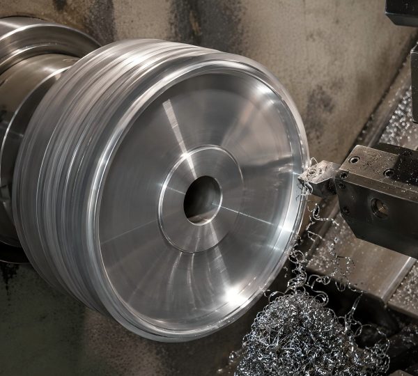
Rough CNC turning removes excess material and generates reference surfaces used throughout the process. This brings the outer diameter, bore, and flange face close to near-net shape.
This step matters because it controls the first datum surfaces for later operations. Runout errors introduced here carry forward into center bore machining and bolt hole drilling. Keeping radial and face runout within tolerance makes the next machining stages more stable.
Center Bore Machining and Concentricity Control
The center bore locates the hub on the axle or spindle. Its accuracy directly affects wheel concentricity and running vibration. CNC turning or boring brings the bore to the final diameter.
Several points need close control:
- Center bore diameter
- Bore roundness
- Concentricity with the outer flange
- Bore surface finish
- Runout at the bore and flange
Runout at the bore translates directly into wheel runout once the assembly is installed. Even small deviations can create vibration problems later.
Bolt Hole Drilling and PCD Accuracy
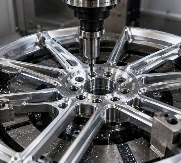
Bolt hole position is machined by CNC milling or a dedicated drilling cycle. The bolt circle diameter, or PCD, hole diameter, hole spacing, and angular position all affect how the wheel seats against the hub flange.
The most important checks include:
- PCD accuracy
- Hole diameter
- Hole spacing
- Angular position
- Chamfer quality
An off-position hole forces the fastener to compensate. This reduces clamping consistency and increases fatigue risk. Each hole is typically spot-drilled, drilled to depth, and chamfered in sequence.
Offset and Mounting Surface Flatness
Offset is the distance from the hub’s mounting face to its centerline. Operators must machine it to a consistent value across the production run.
A warped or stepped mounting face prevents full contact between hub and wheel. This can lead to uneven fastener load distribution and fretting under load. Face turning produces a flat mounting surface, which is verified during final inspection.
Bolt Seat Machining and Chamfer Accuracy
Most wheel hubs use conical bolt seats matched to the fastener taper angle. The chamfer angle must be machined accurately so the fastener makes full, even contact with the seating surface.
If the angle is off, stress concentrates at the seat edge. This reduces the effective clamping force. Chamfer geometry is checked using go/no-go gauges or a CMM probe.
Deburring, Polishing, and Surface Finishing
Burrs form at drilled hole exits, chamfer edges, and turned shoulders. They must be removed before inspection and assembly.
Common finishing steps include:
- Hand deburring
- Vibratory finishing
- Automated brushing
- Edge chamfering
- Finish turning or polishing
Burrs on bolt holes can affect fastener seating and skew CMM measurements. Machinists finish-turn or polish the mounting face and bore to meet the required surface roughness specification.
Final Inspection for Wheel Hub Quality
CMM inspection verifies PCD, bolt hole position, center bore diameter, and offset against the engineering drawing. Runout is measured at the bore and flange. Thread gauges check tapped holes for pitch and depth.
Final inspection usually focuses on:
- PCD and bolt hole position
- Center bore diameter
- Offset value
- Runout and concentricity
- Surface roughness
- Thread pitch and depth
Parts outside tolerance are segregated. Inspection records also feed back into process monitoring to catch drift early.

How Process Control Improves Wheel Hub Machining Quality
Stable fixturing, consistent cutting parameters, and in-process gauging reduce dimensional scatter across the production run. Vibration issues in the field often trace back to runout or concentricity errors introduced during the wheel hub machining process.
Catching these issues at the machining stage costs far less than addressing them after delivery. Manufacturers need process control at every step. This includes blank inspection, machining, in-process gauging, and CMM verification. Better control reduces defects and supports stronger supplier relationships.