
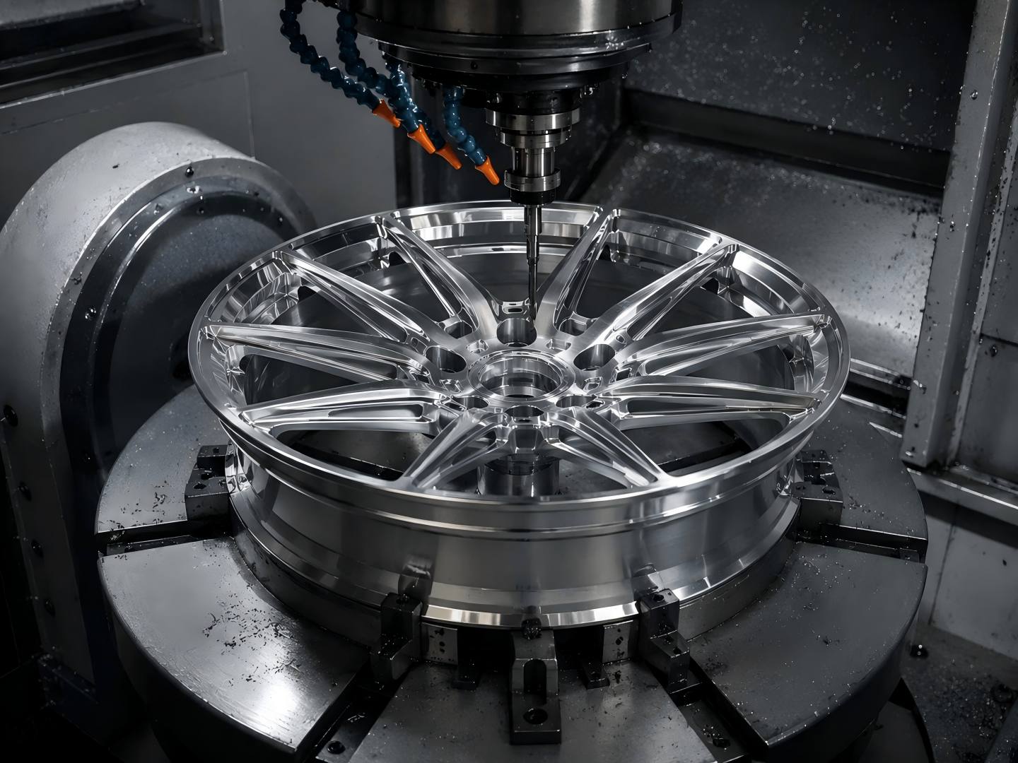
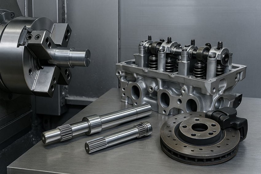
In the automotive parts precision machining, whether you are producing high-volume engine mounts, safety-critical suspension components, or small-batch prototype housings, the part modeling method used in the design phase determines the ease and reliability of subsequent precision machining. Both 3D modeling and 2D drafting during the design phase affect the precision of machining automotive parts. We will focus on practical results: tolerance control, programming complexity, CAM/CNC integration, inspection, delivery cycle, and cost. If you are responsible for part design, mold making, or production planning, this section will help you choose a modeling method that provides predictable accuracy and better production economics.
Differences between 2D and 3D Design in Automotive Parts Precision Machining
In the automotive parts precision machining, the modeling strategy directly determines programming efficiency, tolerance stability, and production reliability. Although 3D and 2D design methods are still widely used throughout the automotive supply chain, their impact on precision machining differs significantly.
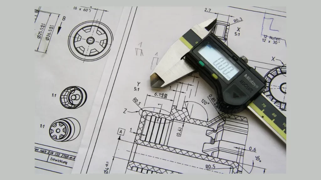
2D design has supported precision machining for decades. In this approach, geometry is conveyed through orthographic and sectional views, along with detailed dimensions. For simple automotive parts such as brackets, gaskets, and drill blocks, 2D drawings remain practical and cost-effective. However, 2D designs require interpretation. Machinists and CAM programmers must mentally reconstruct spatial relationships before generating toolpaths. For complex tolerance chains, such as concentric holes or multi-plane datums, this conversion step introduces risk. In the precision-machining environment for automotive parts, as complexity increases, relying solely on 2D modeling can lead to longer setup times, more conservative fixture strategies, and greater reliance on operator experience.
3D Design Modeling Enhances Automotive Parts Precision Machining
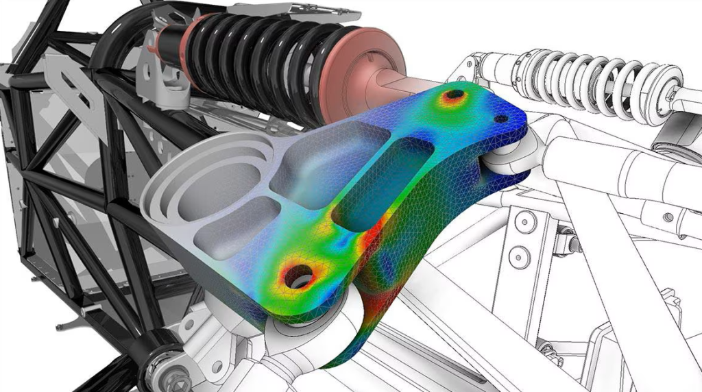
3D modeling fundamentally changes how precision machining workflows operate. Solid models embed geometric relationships directly into the part structure. Features such as fillets, grooves, holes, and surfaces are defined parametrically, meaning changes propagate automatically while maintaining design intent.
For automotive parts precision machining, 3D modeling provides:
- Clear spatial visualization
- Direct CAM data integration
- Associative tolerance definitions
- Reduced programming ambiguity
Furthermore, Model-Based Definition (MBD) directly integrates geometric dimensions and tolerances (GD&T) into the digital model, enabling synchronization of machining and inspection workflows. Improved tolerance clarity leads to improved machining consistency.
The Impact of 3D vs. 2D Machining on the Automotive Parts Precision Machining Performance
Design methodology influences every variable in downstream manufacturing—from toolpath generation to inspection, fixture design, cost, and long-term scalability. In precision machining operations, CAM efficiency determines product quality and delivery speed. With 3D models, toolpaths can be calculated directly from the actual solid geometry. Operations such as roughing, finishing, contouring, and multi-axis machining can all be simulated in a virtual machining environment before production begins.
This capability avoids collisions, optimizes cutting fits, ensures predictable cycle times, and reduces the need for iterative adjustments. In contrast, 2D-based workflows typically require intermediate 3D modeling before programming begins. This additional step increases development time and can lead to geometric interpretation errors. For automotive parts requiring strict control over fan-edge, contoured surfaces, or multi-faceted alignment, 3D-driven precision machining offers significant advantages.
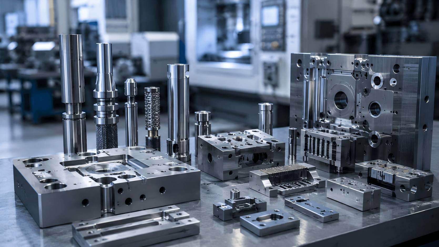
Fixture Design and Benchmarking Strategies
Fixtures determine the repeatability of machining. In the precision machining of automotive parts, 3D modeling enables engineers to design fixtures and digitally verify them virtually. Accessibility to multi-axis machining can be pre-assessed, reducing the number of actual clamping operations required.
Fewer setups yield measurable benefits:
- Reduced cumulative tolerance build-up
- Improved concentricity control
- Shorter production cycles
- Increased part consistency
When machining based solely on 2D drawings, fixture engineers rely more on experience and manual interpretation of the layout. This may be sufficient for simple parts. However, for complex castings or housings, 3D data ensures precise alignment of reference points during machining.
Final Recommendations
The key to automotive parts precision machining lies in the clarity of design and the standardization of manufacturing processes. 3D design and modeling empower modern CAM, simulation, and metrology workflows, resulting in repeatable accuracy and shorter lead times. While 2D drawings still play a role in clarifying simple parts and contract terms, manufacturers and engineers should adopt relevant strategies: use 3D models for manufacturing-critical geometries, retain 2D models where budget allows, and unify benchmarking and verification methods for both models. This balanced approach can improve the quality of automotive parts, accelerate production, and deliver predictable performance.
