PRECISION DIES

Precision Dies

What Are Precision Dies?

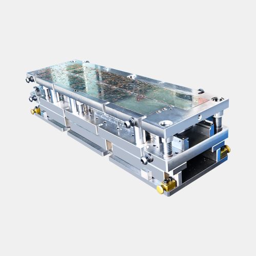
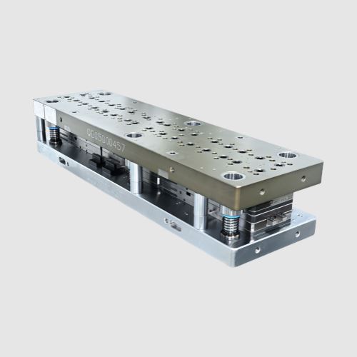
Precision dies are custom stamping tools that cut, bend and form sheet metal into specific part geometries. Each die is developed around a customer's part drawing, material and production volume, then built to run reliably in a stamping press.

You typically need a precision die when a part must hold tight geometry across high volumes. That includes connectors, terminals and battery parts. You also need it when burr control and dimensional repeatability matter downstream.

✓Custom to your drawing
✓±0.005 mm repeatability
✓Design to tryout, in-house

▤Typical Capabilities

Tolerance±0.005 mm (can reach ±0.002 mm)
Tool steel hardness58–62 HRC
Surface finishRa ≤ 0.2 μm
Life cycleUp to 10,000,000 strokes
Die sizeUp to 600 × 2000 mm
Stamping thickness0.05–6 mm (material dependent)
Stamping materialsStainless steel, copper alloys, aluminum, special alloys

Values are typical ranges; actual figures depend on part design, material and volume.

Where Precision Dies Are Used

From microelectronic components to large structural parts, precision dies deliver consistent forming, minimal burrs and stable dimensions.
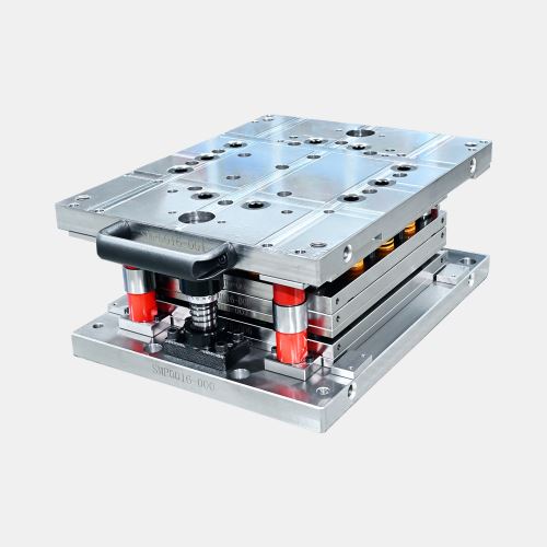
Precision stamping die for automotive components

Automotive Components

Brackets, connectors and structural stamping parts for automotive applications.
Brackets Connectors Battery terminals
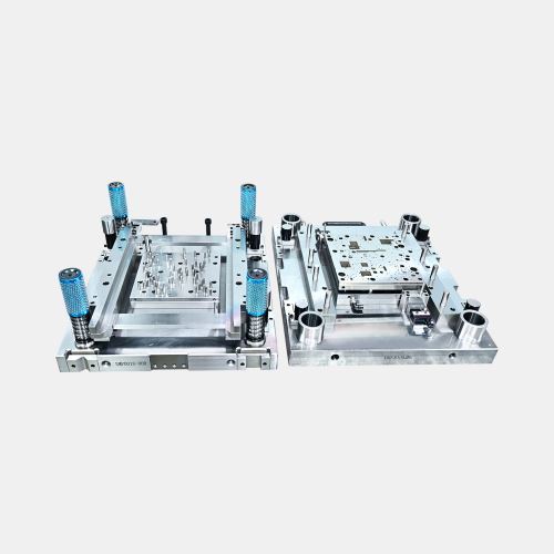
Precision die halves for electronics stamping

Electronics & 3C

Sensor housings, microelectronic connectors and PCB shields for 3C electronics.
Sensor housings Micro connectors PCB shields
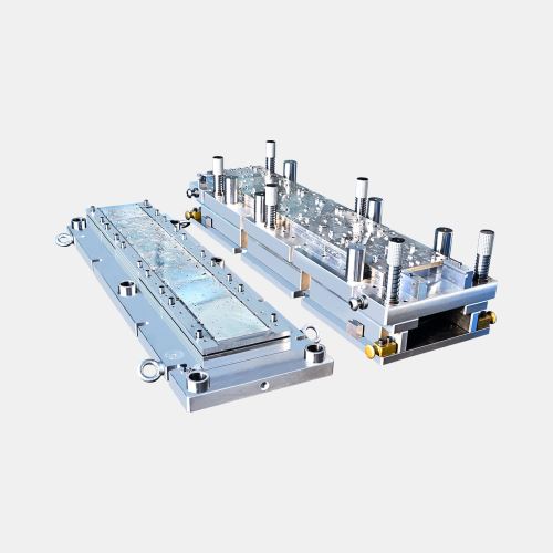
Progressive die set for high-volume stamping

Industrial Manufacturing

High-volume progressive dies for consistent production of complex parts.

Progressive dies High-volume runs

Our In-House Manufacturing Equipment

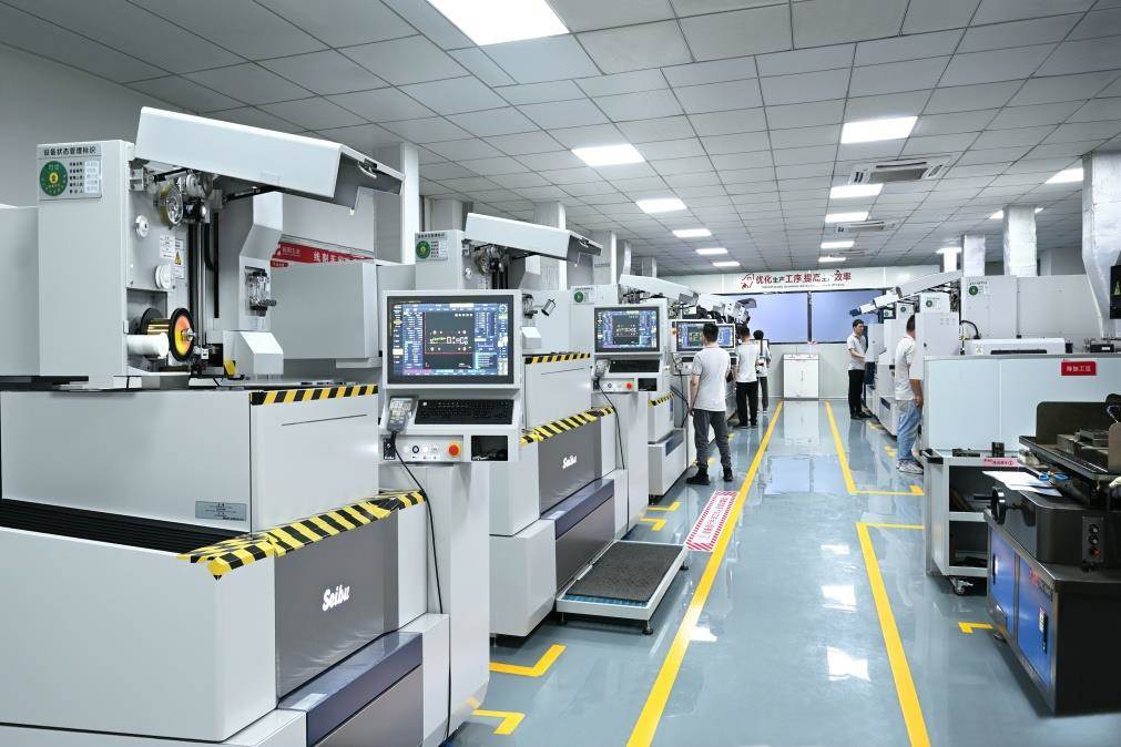
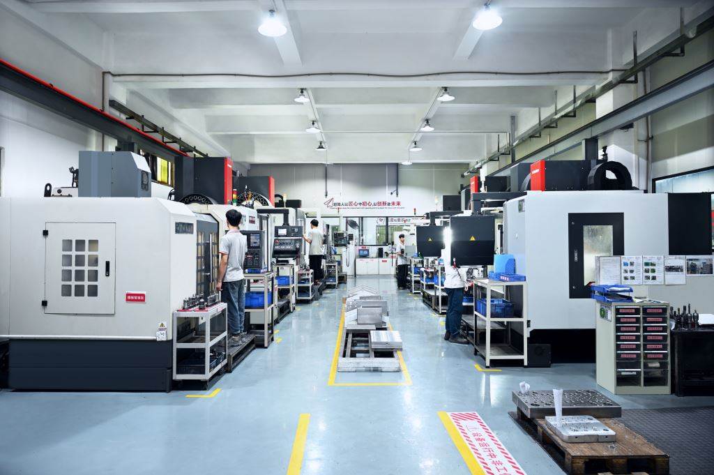
Hover a process to see the equipment. Grinding, EDM and CNC are all completed in-house in one facility, with heat treatment and tryout support.
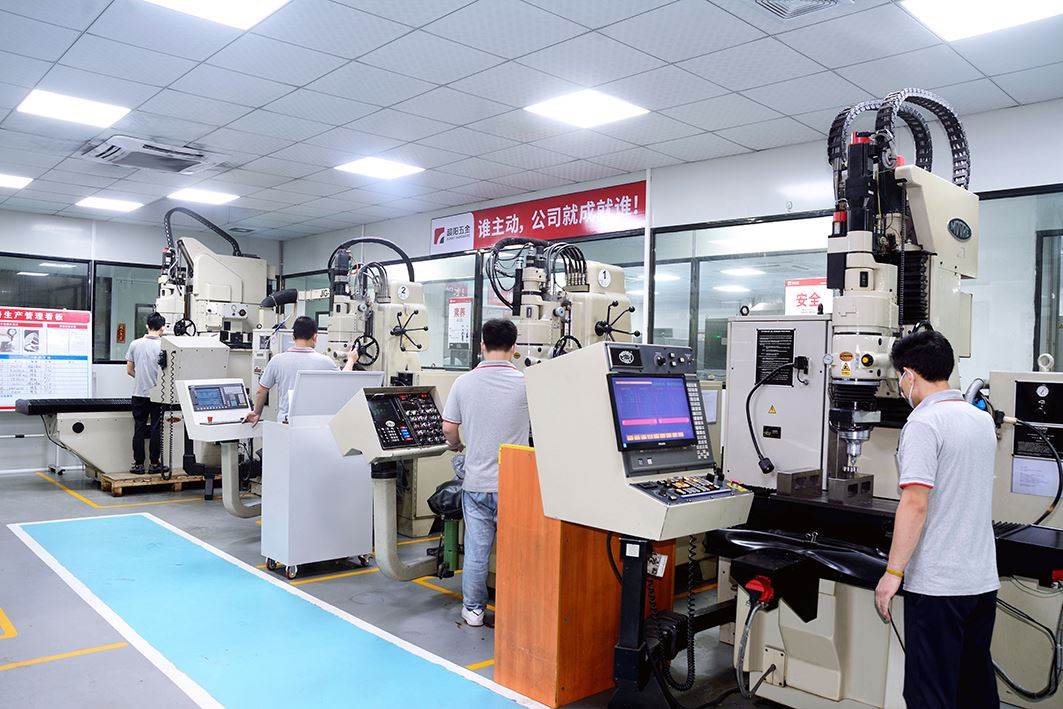
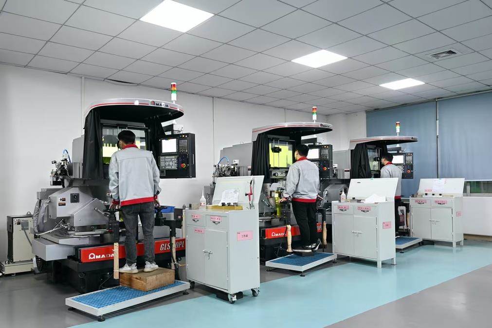
Jig Grinding
Moore (USA) · ±0.001 mm · true roundness ±0.001 mm
Profile Grinding
WASINO · ±0.001 mm · Ra0.05
Wire EDM — water-based
Seibu (Japan) · ±0.001 mm · wire φ0.05–0.3 mm · Ra0.05 / Rz0.1
Wire EDM — oil-based
Sodick (Japan) · ±0.002 mm
High-Speed CNC
YASDA (Japan) · ±0.002 mm · up to 40,000 rpm · 300 × 420 mm
CNC Machining Centers
AWEA · AGMA · Vision Wild · workpieces up to 1600 × 3100 mm
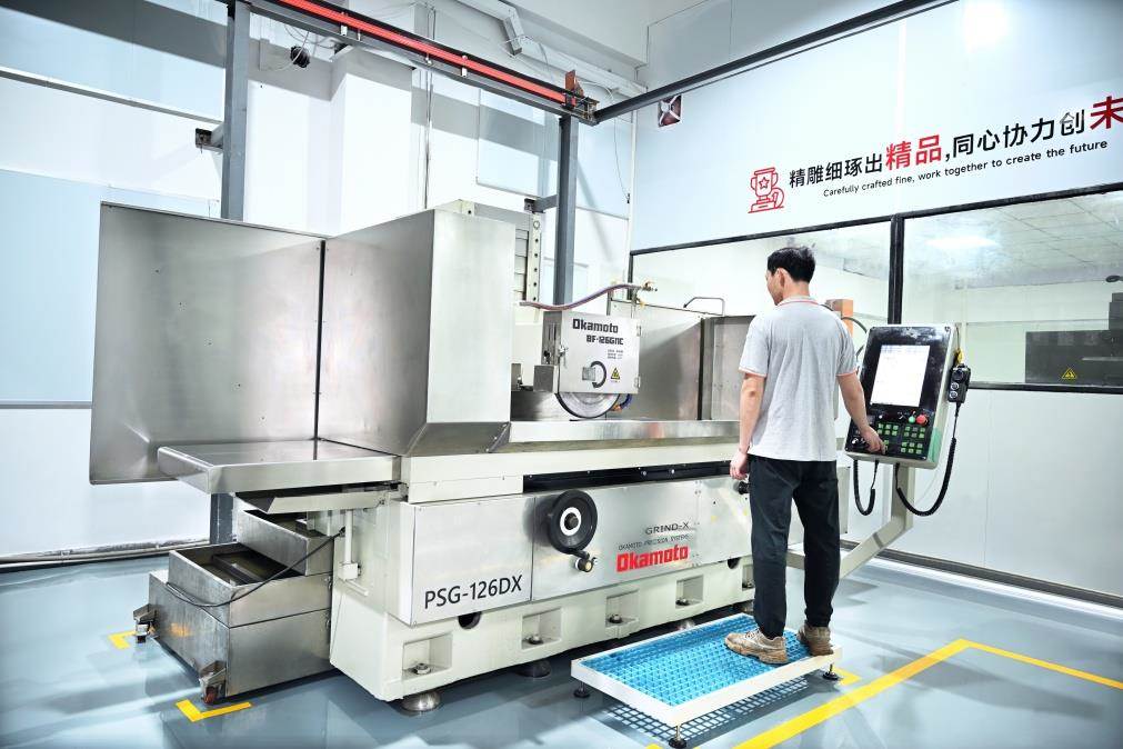
Large Surface Grinding
Okamoto · Chevalier · ±0.001 mm · 600 × 1200 mm · Ra0.02
Small Surface Grinding
Okamoto · Chevalier · ±0.001 mm · Ra0.05 · min groove 0.07 mm
Moore jig grinding machines

One Roof, One Chain

Design, strip layout, machining and assembly in one facility — reducing outsourcing risk and lead time.

Heat Treatment & Tryout

Die components are heat-treated and the assembled die is tested on a press before shipment.

Process Consistency

Grinding, EDM and CNC run under the same quality system, so each component follows one standard.

Quality & Inspection

Every die is checked against the drawing with CMM and optical measurement before shipment. Inspection runs in a controlled-environment lab, so measurements are stable and repeatable.

✓ ISO 9001:2015 certified quality system across design, machining and inspection.
✓ Sample part inspection — first articles checked on CMM and projector against the customer drawing.
✓ Controlled-environment lab — dimensional checks under stable temperature conditions.

Measuring Equipment

In our controlled-environment inspection lab

ISO 9001:2015
Certified quality system
Zeiss CMM
3D coordinate measurement
Trimos 2D Height Gauge
Height & 2D checks
Nikon Profile Projector
Optical profile inspection
Nikon Height Gauge
Precision height measurement
Nikon Measuring Microscope
Fine feature measurement

What Affects Die Design?

Four factors drive how a precision die is laid out and built.

01

Part Geometry

Holes, slots, bends and formed features determine how many stations the die needs and the order of operations.

02

Material & Thickness

Different metals and gauges change cutting behavior, springback and required punch-to-die clearance.

03

Production Volume

Expected run length influences tool steel choice and how wear-prone components are designed.

04

Critical Dimensions

Features holding tight tolerance get dedicated stations and inspection points, not post-stamping luck.

These factors are why a die approach starts with your drawing, material and volume.

Start a Precision Die Project

01

Share Your Drawing

Send a 2D PDF/DXF or 3D STEP/IGES file of the part you want to stamp.

→
02

Tell Us the Basics

Add material, thickness and expected annual volume or initial run size. NDA can be signed upfront.

→
03

We Review & Discuss

Our engineers check formability and strip layout, then come back with questions or a die approach.

Precision Dies — Common Questions

What information should I provide to start a die project?+
At minimum: a 2D drawing or 3D model, material and thickness, and expected volume. Critical dimensions and plating requirements help us evaluate the die layout more accurately.
Can you build a die from my own drawings?+
Yes. Most precision dies are built from customer-supplied drawings or CAD files. Send the part drawing and the engineering team will review formability and tooling approach.
Can you supply both the die and the die set / mould base?+
Yes. We build precision dies, die sets and non-standard mould bases, so the die and its structural support can come from one supplier. See our tooling die sets for the standard range.

Have a Question About Dies?

Send your part drawing and requirements. The engineering team will review feasibility and come back with questions or a recommended approach.

Send Your Drawing

Need a Custom Stamping Die?

Send your part drawing, material requirements and volume expectations. We'll review feasibility and come back with questions or a recommended next step.

Send Your Drawing
Scroll to Top