Application Industries

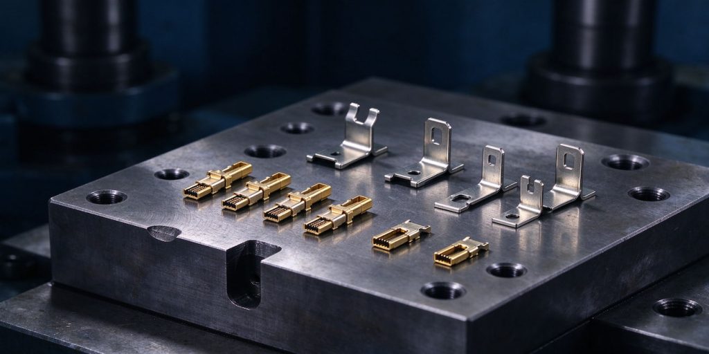
Automotive stamping tolerances precision die insert
Application Industries

Why Are Automotive Stamping Tolerances So Tight?

Automotive stamping tolerances are not tight because of an industry rule. They are tight where the part’s function demands it — and relaxed where it does not. A terminal’s contact surface, a bracket’s locating hole, and a cosmetic outer edge carry very different limits on the same drawing. Understanding where the tightness comes from changes which features you chase and which you can safely leave loose. You must then translate these requirements into a process that can produce and verify the part consistently. Material variation, springback, die wear, and measurement methods all influence dimensional results. So engineers and buyers should check each factor when reviewing a drawing or evaluating a supplier. Where Automotive Stamping Tolerances Come From The pressure does not start at the stamping press. It starts at the assembly line and the function of the finished part. Why automotive parts pull specific features in tight, and why the same part can carry both very tight and very loose limits, both trace to that starting point. Why Do Automotive Parts Demand Tighter Tolerances Than General Stamping? Why are automotive stamping tolerances so tight? The best answer comes from what the part has to do, not from a typical value. Three mechanics drive the tightness: Automated assembly. Robots and feeders cannot adjust a part that does not fit. A locating hole that drifts can stall a line or jam a fixture. Function stacking. A connector terminal’s contact force, insertion force, and retention all depend on dimensions that must hold across millions of pieces. Failure cost. A drifted feature shows up as a quality issue inside the vehicle — far more expensive than a rework at the press. The drawing sets how tight each feature gets. It usually references the customer’s own standards or an internal specification for critical dimensions. Automotive stamping tolerance standards may cover dimensions that carry no individual callout. Critical features often need individually defined dimensional or geometric tolerances, based on their functional requirements and the customer’s specifications. Which Automotive Features Set Stamping Tolerances? The useful way to read an automotive stamping drawing is stamping tolerance by feature. Each feature earns its limit from its role: Automotive connector terminal stamping tolerance — contact areas, locking lances, and mating surfaces carry the tightest limits, because they define electrical and mechanical function. Automotive sheet metal stamping tolerances — locating holes and critical assembly interfaces stay tight, while general profile and bend positions can relax. Motor lamination stamping tolerance — tooth profiles, bore concentricity, and lamination consistency define motor performance, so they carry strict limits. Cosmetic edges, clearance holes, and non-functional surfaces — these can run at general tolerances without hurting assembly or function. So the skill is deciding which bucket a feature belongs to. Over-specifying a clearance hole buys nothing. Under-specifying a terminal contact face invites field failures.   What Turns Automotive Stamping Tolerances into a Process Plan? Between the drawing and the shipped part sits a chain: functional requirement → critical feature → process variation → measurement and process control. A drawing states where the part should be; the die, the press behavior, and the inspection method decide whether it gets there. Every link either wins the tolerance or loses it. Why Does Springback Move the Part After Forming? Every bent or drawn feature springs back a little when the press releases. In short, formed sheet metal partially recovers its shape after forming ends. So it can shift bend angles, formed heights, and other dimensions away from their intended values. High-strength steel stamping can bring significant springback, but the effect depends on grade, thickness, geometry, and forming conditions. Die designers compensate with over-bending or coining steps. Yet the compensation must match the actual grade and thickness. Springback is not a fixed number you can look up. It shifts with material grade, sheet thickness, bend radius, and tooling gap. A die tuned for one coil can drift when the next coil behaves differently. For a deeper reference on how advanced high-strength steels behave during forming, the advanced high-strength steel stamping guidelines cover the material side in detail. Why Do Parts Drift After the First Thousand Strokes? Tolerances on day one are not the same as tolerances at stroke 200,000. Punch edges wear, die clearance grows, and burr height climbs. So every buyer should ask early: how does die wear affect stamping tolerance? The answer decides whether a supplier plans for wear or waits for it. Where wear concentrates, hard carbide inserts and replaceable punches are common choices. Shops often schedule maintenance by stroke count, depending on the application, material abrasiveness, and feature criticality. In short, a supplier who treats dies as disposable until parts fail is betting your line against wear. Which Measurements Count on a CMM Report? If you cannot measure a tolerance, treat it as a guess. Automotive prints normally pair each critical feature with a verification method. CMM covers positions and profiles where the feature justifies it; air gauges or micrometers cover bores; optical projectors cover contours. Position, flatness, roundness, and repeatability are different indicators. Mixing them up produces reports that look fine and prove nothing. The check that matters most: does the measurement reference the same datum as the drawing? The inspection setup should follow the datum scheme on the drawing. If the reference or the feature evaluation differs from the specified method, the report may not show whether the part meets the requirements. So confirm the method suits the tolerance, and check the reported results against the drawing’s acceptance criteria. What Should You Confirm Before Specifying Automotive Stamping Tolerances? Before you finalize a drawing or select a shop, run four checks. This is also what to look for in a stamping supplier in practice: Which features actually affect assembly or function? Tighten those, relax everything else. Is each critical tolerance paired with a named measurement method and the same datum as the drawing? Has the tooling plan absorbed springback and planned for wear — not just quoted the press speed? Does the shop hold
Semiconductor precision machining probe card fixture
Application Industries

Why Is Semiconductor Precision Machining So Demanding?

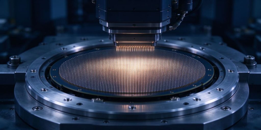
Why Is Semiconductor Precision Machining So Demanding? Semiconductor precision machining covers parts that operate inside wafer fabs and chip assembly lines—wafer-handling fixtures, probe cards, lead frame dies, and the tooling that shapes them. Tolerances land in the micron range, and the materials resist normal cutting. Knowing why the bar sits so high matters. It tells you which specs actually drive performance and which are just noise on a drawing. Demanding here is not marketing. The strictness traces back to process risk. A positioning feature that locates a wafer affects every layer aligned on it. A probe tip that lands off-pad fails a test. Each part’s requirement level depends on its role in that chain, not on a blanket industry rule. The sections below cover where the strictness comes from, how it translates into materials, tolerances, and surfaces, and what to verify before you pick a supplier. Where the Strictness of Semiconductor Precision Machining Comes From The pressure does not start at the machine shop. It starts at the device and travels down through the equipment that makes it. In semiconductor precision machining, the chain starts at the wafer. This section shows how requirements distribute across parts by their function in the error chain, and why the cost of a miss justifies hard minimums. Why Do Semiconductor Parts Need Tight Tolerances? Device features are nanometer-scale. That alone does not force every carrier, bracket, or fixture to the same size tolerance. What matters is where the part sits in the chain. A wafer locating feature positions every exposure on that wafer. A probe pattern decides whether test needles contact the right pads. These parts carry functional requirements. Support brackets do not. The useful framing for why semiconductor parts need tight tolerances is not “the industry is strict.” These specific features directly influence device results. Position error in a locator becomes overlay error in lithography. The magnification happens step by step, from fixture to stage to exposure. Yield loss from positioning errors is a core concept in semiconductor manufacturing. What Does a Failed Part Cost on a Production Line? Precision here is about yield — the share of usable chips per wafer. One mislocated wafer can misalign an entire layer. One drifting probe pattern can take out an entire test station. A defective component can cause localized quality issues, disrupt a test process, or contribute to production downtime, depending on its function and where the failure occurs. This potential impact is why critical tooling and fixture requirements must be tied to specific performance risks and verified through inspection. Fabs run around the clock, and wafers carry many high-value dies. That is why requirements are written as hard minimums, not “as tight as practical.” The cost of a miss is not rework. It is lost production. What Demanding Semiconductor Precision Machining Requires Strictness lands in three checkable places: material behavior, tolerance definition, and surface condition. This section turns “high precision” into engineering requirements you can verify. It closes with a short checklist for evaluating a shop. Which Materials Make Semiconductor Machining So Hard? Most semiconductor tooling is not aluminum. It is tungsten carbide, hardened tool steel, ceramics, and engineering plastics. Each limits machining and verification differently. Machining tungsten carbide for semiconductor fixtures is hard mainly because of its hardness and wear resistance. Carbide blunts ordinary cutters quickly. The right process depends on grade and geometry — grinding for round features, EDM for shapes a wheel cannot reach. Hardened steel (typically 55–62 HRC) often needs grinding or wire EDM. But the choice depends on part shape, stock removal, heat-treatment state, and surface integrity requirements—not hardness alone. Ceramics add brittleness and thermal sensitivity. The difficulty varies with ceramic type, processing stage, and target surface quality. PEEK and similar plastics raise different issues: dimensional stability under heat, tool sharpness, and avoiding smeared surfaces. Each material requires different processes and a verification method. How Tight Is Tight for a Semiconductor Fixture? No single number applies to all fixtures. Tolerance is set per feature, by function. A locating-pin position, a bore roundness, a contact-face flatness, and a repeatability spec are different indicators. Mixing them up is where over-specification starts. Semiconductor machining tolerance microns describe the working scale, not a universal value. Ask what each critical feature needs: position relative to which datum, flatness over which area, roundness at which bore. The drawing should name the feature, the value, and the measurement method. Why Does Surface Finish Matter for Semiconductor Tooling? Surface requirements follow function. A contact face that seals or mates may need a low Ra and no burn layer. A non-contact surface does not. Surface finish requirements for semiconductor tooling therefore vary by feature, not by a single standard applied to every face. Underneath roughness sits surface integrity. Grinding carbide or hardened steel too hot can leave a burned or re-cast layer. It can look fine and fail early. For critical surfaces, the specification may need to address more than Ra. Depending on the application, it may also define acceptable surface integrity, limits on grinding burn or EDM-related damage, and requirements for dimensional stability. Select these requirements based on the component’s function and verify them using suitable inspection methods. Which Parts Need This Level of Control? Not every semiconductor part is micron-critical. The parts that need tighter control are those whose dimensions, positioning, or surface condition directly affect product handling, testing, tooling performance, or equipment accuracy. Wafer handling fixture machining — carriers, chucks, and end-effectors that grip wafers. Repeatability, flatness, and particle-free surfaces matter more than absolute size. Semiconductor probe fixture precision — probe cards and test fixtures where hole patterns must match device pads. Lead frame die machining — stamping tools that run at high speed, where every stroke must land the same. Support brackets, covers, and frames that never touch product can use standard CNC tolerances and finishes. Over-specifying those wastes budget without buying reliability. What Should You Confirm Before Specifying Semiconductor Tooling? Start by looking for what to expect in a semiconductor machine shop

Scroll to Top