Stamping Dies Fabrication

Stamping Dies Fabrication
Chaoyang blog

How CAD/CAM Optimization Enhances Stamping Dies Fabrication Accuracy?

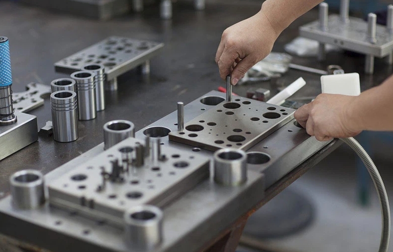
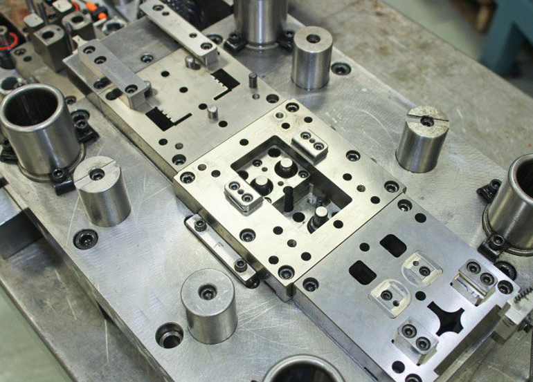
Manufacturers expect stamping tools to deliver stable accuracy across millions of cycles. However, traditional manual processes often introduce inconsistencies. CAD/CAM optimization changes this reality. It offers predictable modeling, faster design cycles, and tighter tolerances. Today, most high-performance Stamping Dies Fabrication workflows rely on advanced digital integration to reduce design errors and improve tool performance. Companies in automotive, consumer electronics, and connector manufacturing report that optimized CAD/CAM systems cut development time by up to 30% and reduce revision loops. These benefits make digital optimization a core requirement for modern tooling teams. Enhanced Design Precision Through Advanced CAD Modeling CAD modeling sets the foundation for die accuracy. High-resolution 3D models make it easy to verify each surface, corner radius, and relief area. Engineers use parametric features to control geometry and quickly adjust dimensions. This reduces mistakes and allows faster design iterations. CAD systems also support interference checks to detect fit issues between punches, dies, plates, and guide components. Many shops combine CAD with simulation tools to verify deformation patterns before machining. This step eliminates trial-and-error adjustments and protects the final Stamping die from misalignment problems. When CAD design is clean and consistent, downstream machining becomes far more accurate. Improved Toolpath Efficiency with CAM Optimization CAM optimization transforms a static CAD model into an efficient machining strategy. Modern CAM systems generate toolpaths that maintain consistent cutter engagement. This improves surface finish and dimensional stability. Advanced functions such as high-speed machining, trochoidal milling, and adaptive clearing reduce cutter load. These strategies also extend tool life, which helps maintain consistent accuracy throughout long machining cycles. When machining die components like punches, inserts, and form blocks, CAM optimization directly affects the performance of the finished tools. It ensures the geometry matches the CAD model with minimal deviation. Reducing Human Error with Automated Simulation and Verification Simulation helps teams validate toolpaths before cutting steel. CAM systems simulate cutter motion, spindle load, and collision risks. This process reduces human error and prevents costly crashes. Simulation also predicts tool deflection and machining heat buildup—two familiar sources of dimensional drift. When engineers review these simulated data points, they can adjust feed rates, cutter types, and workholding strategies before actual machining. Many companies report that digital simulation reduces machining problems by more than 40%. This dramatically improves the accuracy of final Stamping Dies Fabrication and lowers rework costs. Better Material Utilization and Tolerance Control CAD/CAM optimization ensures that material allowance, stock thickness, relief dimensions, and tolerance zones stay consistent throughout the design and machining workflow. Engineers specify detailed tolerance limits in the CAD stage, and CAM systems apply them to machining operations. This ensures consistency from roughing to finishing. It also maintains tight tolerances on cutting edges, form radii, and clearance areas. These areas directly affect stamping quality. When dies maintain precise geometry, stamped parts show fewer burrs, more consistent springback, and improved fit with downstream assembly. Accelerating Workflow Through Digital Integration Digital integration connects CAD, CAM, CMM measurement, and ERP/MES systems. This creates a closed-loop workflow. Engineers compare machined components with CAD data using coordinate measuring machines. When deviations appear, they update CAD/CAM models and apply corrections immediately. This reduces lead time and maintains accuracy during complex multi-stage Fabrication. Digital integration also simplifies version control. It ensures that all engineers, machinists, and quality teams use the same dataset, minimizing communication errors. Real-World Applications Across High-Precision Industries Industries such as automotive connectors, EV battery components, and consumer electronics benefit from CAD/CAM-optimized tooling. For example, connector manufacturers require ultra-tight tolerances on punch profiles, often within ±0.002 mm. CAD/CAM optimization enables consistent machining of these micro-features. Smartphone metal-frame suppliers use digital simulation to control springback during forming. Meanwhile, EV battery stamping lines rely on optimized die geometry to avoid burrs that could damage batteries. These real-world applications show that CAD/CAM is not simply an upgrade—it is essential for competitive Stamping Dies Fabrication. CAD/CAM Optimization Drives High-Accuracy Stamping Dies Fabrication CAD/CAM optimization provides measurable improvements for modern tooling teams. It reduces errors, improves machining efficiency, and strengthens accuracy across all die components. Manufacturers benefit from lower rework rates, faster development cycles, and more stable tool performance over millions of strokes. As demand for thin-metal components and complex geometries continues to rise, optimized CAD/CAM workflows will remain essential for high-quality Stamping Dies Fabrication.

stamping dies fabrication
Chaoyang blog

Understanding Tolerances and Fit in Stamping Dies Fabrication for High-Reliability Parts

In stamping die fabrication, precision is everything. The slightest deviation in tolerance can result in misaligned parts, poor quality, and expensive production delays. Engineers and manufacturers prioritize tight tolerances and optimal fit to ensure high-reliability components. This demand grows stronger in industries such as automotive, electronics, and aerospace, where failure isn’t an option. Understanding tolerance involves knowing the acceptable degree of variation in part dimensions. Fit refers to how different components come together in an assembly. When both are controlled effectively, stamped parts function correctly and maintain structural integrity. With stamping dies fabrication, precision tooling must account for these variations without compromising efficiency or throughput. Key Types of Tolerances and Their Functions Dimensional tolerance defines the acceptable size range for stamped parts. It ensures that the part fits its mating component without excessive play or tightness. For instance, a too-loose tolerance leads to vibration and wear, while a too-tight one causes assembly issues. That’s why manufacturers must select the right balance. Geometric tolerance controls the shape, orientation, and location of features. It includes aspects like flatness, perpendicularity, and concentricity. These tolerances become crucial in complex assemblies, where even slight deviations can disrupt the entire system. Accurate geometric tolerances ensure that parts function well, especially under load. Fit Classifications and Their Industrial Implications Fits are categorized into three classes: clearance, interference, and transition. Clearance fits allow for easy assembly and are often used in applications that require movement. Interference fits require forceful assembly and provide secure joints in high-load areas. Transition fits offer a compromise between the two. Choosing the correct fit type is critical. Each has unique mechanical implications. For example, automotive suspension parts often utilize interference fits to achieve rigidity and stability. Meanwhile, consumer electronics lean toward clearance fits for ease of maintenance. Understanding these distinctions helps tailor the die design to the application. Die Design Strategies to Control Tolerances Toolmakers employ several strategies to maintain tight tolerances in stamping dies. High-quality tool steel, precision machining, and CNC technology are standard. These tools enable micro-level adjustments, ensuring repeatability over thousands of cycles. Moreover, modular die construction enables easier part replacement without requiring retooling of the entire system. Additionally, simulation software plays a role. Engineers use it to model stresses and deformation during the stamping process. This predictive insight enables preemptive changes to the die geometry, reducing trial-and-error and material waste. Consequently, the final product meets tolerance requirements from the first run. Material Behavior and Its Influence on Fit Different materials behave differently during stamping. Aluminum, for instance, deforms more easily than steel. As a result, allowances must be made for spring back—the tendency of a metal to return to its original shape after stamping. Failure to account for this results in tolerance errors and poor fit. Toolmakers use forming simulations and empirical data to predict and compensate for springback. Material thickness, grain direction, and coating also impact tolerance behavior. Therefore, a holistic understanding of material science is crucial for successful stamping die fabrication. Quality Control Methods to Ensure Compliance Maintaining quality requires rigorous inspection. Coordinate Measuring Machines (CMMs) and optical scanners are commonly used to measure critical dimensions. These tools detect minute variations, ensuring each part falls within specified tolerances. Statistical Process Control (SPC) further helps identify trends and correct issues before defects occur. First Article Inspection (FAI) is another essential step. Before mass production, engineers validated a sample part against all design specifications. This prevents costly rework and builds confidence in the die’s performance. The combination of advanced tools and disciplined methodology guarantees reliable outcomes. Reducing Costs by Managing Tolerances Effectively Tighter tolerances often mean higher production costs. Precision machining, specialized tools, and rigorous QC all add to the budget. However, not all parts require ultra-tight tolerances. Over-engineering leads to unnecessary expense. That’s why innovative tolerance management is becoming a key factor in modern stamping dies fabrication, focusing on critical areas while allowing others to be relaxed. Design for Manufacturability (DFM) plays a crucial role in this process. It encourages collaboration between design and production teams to find the optimal balance, maintaining functionality without increasing costs. By aligning DFM principles with bright stamping dies fabrication strategies, manufacturers can focus resources where they matter most, ensuring part quality without sacrificing profitability. Achieving High-Reliability with Precision in Stamping Dies Fabrication Stamping die fabrication hinges on mastering tolerances and fit. These elements determine whether a part performs flawlessly or fails under stress. Engineers must balance precision, cost, and material behavior to create reliable components that meet specific requirements. By understanding fit types, applying accurate tolerances, and utilizing advanced tools, manufacturers can ensure the production of high-reliability parts.

Scroll to Top